Mesh Light
Mesh Lights are a type of direct light source whose shape comes from a mesh item in the scene. Like instances, multiple mesh lights with different positions and orientations can refer to the same mesh item. The prototype mesh itself is hidden during rendering. When direct illumination is calculated, the probability of sampling points within a particular triangle of the Mesh Light is proportional to the triangle's surface area, resulting in sample points being evenly distributed across the light.
The main advantage of Mesh Lights over luminous geometry is to reduced shading noise, especially if the light has thin areas and the surface being shaded is diffuse or rough. This is because luminous geometry relies on indirect (BRDF-based) sampling, while Mesh Lights can also use direct (area-based) sampling.
Note: Mesh Lights generate caustics like other direct light types. Direct Caustics need to be enabled in the Render Global Illumination > Caustics settings, and caustics only show in final renders, where photon tracing is calculated.
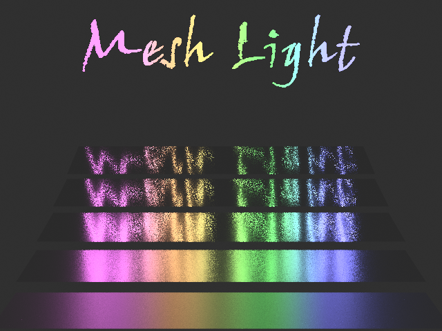
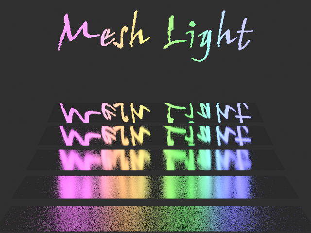
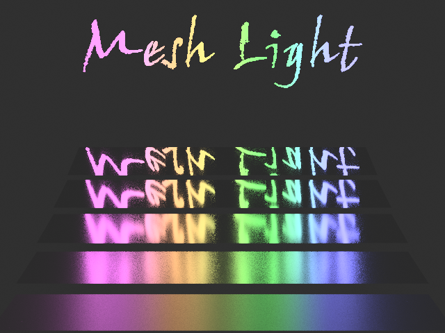
In the following example, the text was modeled and used as the shape of a Mesh Light. The rectangles are reflective with roughness values of 2%, 4%, 8%, 16% and 32%. Notice how the Mesh Light greatly reduces noise on the rough surface. Direct sampling is noisier on the smooth surfaces, but Multiple Importance Sampling (MIS) resolves that problem. Render times were roughly equal for all three images.
Mesh Light: Indirect Sampling Only:
Mesh Light: Direct Sampling Only
Mesh Light: Multiple Importance Sampling (MIS)
To add a Mesh Light to your scene, open the Item List, click Add Item > Lights > Mesh Light. Once added, specify the item used as the Mesh Light shape in the Mesh Light > Mesh field and then set the other Rendering options.
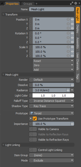
Mesh Light Properties
• Name - this data field displays the current item name. You can easily change it by clicking within the field and typing the new name.
The following Transform options are available:
• Position - allows you to numerically position the light item in XYZ space.
• Rotation - allows you to numerically set the rotation of the light item.
• Scale - allows you to numerically set the size of the light item. This scale transform is a multiplier of the Height and Width options.
• Reset - resets the selected transform values to (0,0,0) returning the items back to their default state.
• Zero - resets the chosen transform property values to '0', leaving the Center position and Mesh position intact. This is done by adding an additional transform item to the Mesh Item's channels with an inverted version of the current values. This is useful to allow, for example, a joint to have a base value of 0,0,0 but still be located away from the World Origin.
• Add - adds additional Transform items to the associated item or, if they do not yet exist, it simply adds them. Transform items are the channel groups that store the actual transform values, controlling any item's position, rotation, and/or scale. You can add as many transform items as you want for any transform property desired. Adding additional Transform items produces an additive effect where each transform group is evaluated before the next, and so on. Additional item transforms are evaluated in their order in the Channels list, from the bottom upwards.
Note: It should be noted that by default, new items do not have any transform items associated with them (even though they are visible here within the Properties panel). This is useful as an optimization, as only the necessary transforms are created on an as-needed basis, reducing scene overhead.
There are several actions that add these base transform items. One is by simply transforming the target item with one of the various transform tools or by editing the values input fields. This action causes the particular transform item to be added automatically to the Channels viewport list. Due to this fact, you may need to specifically create item transforms when Referencing, because in order to override the channels in the master scene, they must first exist.
The following Mesh Light options are available:
• Render - allows you to select from three choices: when set to Default, you can enable/disable lights using the visibility function ![]() of the item list. When the light is visible, it contributes to the final rendered scene and, when invisible, it does not. On some instances you may prefer to fix this state, setting the light as On (enabled) or Off (disabled) regardless of visibility. Also useful for workflows that auto toggle visibility, saving you from manually enabling lights for test renders.
of the item list. When the light is visible, it contributes to the final rendered scene and, when invisible, it does not. On some instances you may prefer to fix this state, setting the light as On (enabled) or Off (disabled) regardless of visibility. Also useful for workflows that auto toggle visibility, saving you from manually enabling lights for test renders.
• Dissolve - when the Dissolve function is set to any value above 0%, the light's overall effect on the scene attenuate as the value increases. When set to 100%, the light's effect on the scene is completely disabled. This function provides a convenient way to dim a light's effect within a scene.
• Radiance - controls the intensity of the light and uses the standard physically-based unit of Watts per volumetric meter. As you would expect, increasing this value increases the amount of light coming from the Mesh Light and decreasing the value reduces the light intensity. With Mesh Lights, the area of light generated in the scene is very small and therefore large values are likely necessary to illuminate the scene how you would expect.
• Light Color - change the color of the Mesh Light. For more information, see Color Picker Viewport.
• Falloff Type - light in the real world isn't a uniform brightness; its intensity diminishes with distance. Photographers may be familiar with the concept that a light is a quarter as bright at twice the distance away, known as the Inverse Square Law. Modo lights default to this setting, providing a realistic way to light a scene. However, there are times when you may not wish to have this behavior, so three falloff type options are provided:
• None - no falloff; light is consistently bright across its distance.
• Inverse Distance - light is half as bright at twice the distance.
• Inverse Distance Squared - default behavior; light is a quarter as bright at twice the distance.
• Shadow Type - offers options between Ray Traced, None and Deep Shadow Maps. In situations where you want a light to cast a shadow, Ray Traced gives the most accurate results. The traditional hard edge of ray traced shadows can easily be softened using Spread Angle value in any light item. Deep Shadow Maps are useful for volumetric lights and fur rendering, where a great deal of calculations are required to produce shadows; producing similar results to ray traced shadows while reducing the number of calculations.
• Prototype - this option lists the procedural meshes in your scene. Select which Prototype to use as the base Mesh Light transform source. The prototype mesh itself is hidden during rendering.
• Use Prototype Transform - enabling this option locks the Mesh Light transforms to the Prototype Mesh item. You can position the Mesh Light by positioning the Mesh item being used as its prototype. By default, this option is enabled. For more information on how this option works, see Using Prototype Transforms for a Mesh Light.
Note: Scenes created in previous versions of Modo load with this option disabled.
• Importance - Modo uses an adaptive light sampling method to evaluate lighting in a scene. This option allows you to control illumination sampling using a single global value, producing better results in less time. In rare cases, where adaptive sampling isn't producing the desired outcome, an individual light's Importance value can be adjusted, acting as a multiplier to the lights evaluated importance. Changes in Importance are relative to other lights in the scene, influencing it one way or the other as more or less important, in effect increasing or decreasing its sample allocation from the total number of possible Light Samples, all while remaining fully unbiased.
• Visible to Camera - you can enable this option to make the light itself visible to cameras. The size of the visible light is determined by the Spread Angle attribute.
• Visible to Reflection/Refraction Rays - you can enable either or both of these options to make the light itself visible to reflective and/or transparent surfaces. The size of the visible light is determined by the Spread Angle attribute.
• LPE Label - you can provide a label name here, which appears as the label for any Light Path Expression output you generate for this light. See Rendering with mPath.
The following Light Linking options are available:
• Control Light Linking - illumination on a surface is generally controlled by the Shader item in the Shader Tree. Within the shader, it's possible to control a light's effect on a surface with Light Linking. As its name describes, it links the illumination affects of a group of lights to specific items or material groups. When the Control Light Linking option is enabled on a light item, it acts as an individual light-specific override to the shader, allowing you to Include or Exclude a specific light's illumination on a group of items.
• Item Group - determines the specific group of item layers in the scene that is affected by the Light Linking. The group needs to be defined in the Groups viewport panel. This can be done easily by selecting the target items while in Items mode and then, in the Groups palette, click the New Group button. Define a name for the group in the pop-up dialog and choose the From Selected Items option and click OK to accept. Once the group is defined, select the named group here.
• Mode - determines whether the light is Included, meaning it only affects the items in the specified item group, and Excluded by all other surfaces, meaning it is ignored by any items in the specified item group.
Using Prototype Transforms for a Mesh Light
The following procedure is a simple example, which demonstrates how to lock the Mesh Light transforms to a selected mesh in your scene and to reposition the Mesh Light by moving the Mesh item.
To apply Prototype Transforms:
| 1. | Open the Render layout. |
| 2. | Add a Ground Plane to your scene. Open Item List, click Add Item, expand Volumes, and then double-click Ground Plane. |
| 3. | In the Properties panel, open the Ground Plane tab and set the Transform > Scale values for X, Y, and Z to 2431.0% |
| 4. | Add a number of other procedural meshes to your scene. Open the Mesh Ops tab, click Add Operator, expand Mesh Operations > Create and then double-click Toroid. |
Tip: If you do not see the Mesh Ops tab, click the + icon and then click Data Lists > Mesh Ops to add the tab.
| 5. | Repeat Step 4 and add the following procedural meshes: |
• Sphere
• Cone
• Cylinder
| 6. | Align the procedural meshes to display in a line on the X axis. Select a Mesh item and then press W. Move the handles to reposition each mesh. |
![]()
| 7. | From the menu bar, click Render > Open Preview and then click the arrow to render your scene. Notice, the prototype mesh itself is hidden during rendering. |
Tip: You can also open Preview by pressing F8.
![]()
| 8. | In the Item List, select the Mesh Light item. |
| 9. | In the Properties panel, open the Mesh Light tab, under the Mesh Light properties, set Prototype to use Cylinder. Notice, the Cylinder prototype mesh is hidden during rendering. |
![]()
| 10. | In the Item List, select the Cylinder, press W and reposition it. |
The Mesh Light is repositioned to the location where you have moved the Prototype mesh item; Cylinder.
![]()