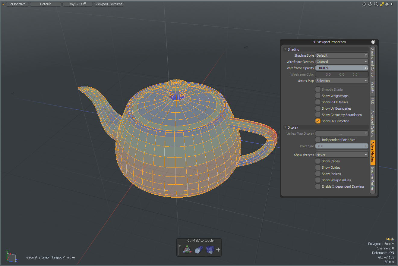
3D Viewport Properties
Allows you to further customize the display of elements within a viewport. The default interfaces apply varieties of these options to their custom workspaces, however, they have been fine-tuned to the degree that they rarely need adjusting.
If required, you can easily access the display menu options by clicking on the gear icon in the upper right corner of the viewport, or moving the pointer over the target viewport and pressing O to open the pop-up menu.
You can dismiss the window by clicking anywhere in the interface.
Note: Edits are made per-viewport.
Drawing and Control
View and Shading
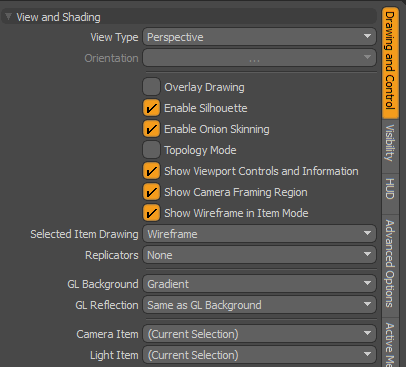
Note: The Enable Silhouette, Topology Mode and Show Weightmaps options are all incompatible with each other and therefore cannot all be enabled at the same time. The Show Weightmaps option supersedes the Enable Silhouette option and the Topology Mode options supersedes both.
|
View Type |
Choose from the various view types covered in the 3D (OpenGL) Viewport section: Top, Bottom, Back, Front, Left, Right, Perspective, Camera and Light. |
|
Orientation |
For the orthogonal views only, you can control upright rotation angle in 90° increments. |
|
Overlay Drawing |
For custom draw items, such as locators, cameras and lights (that have no inherent geometry) this option enables an X-Ray style of viewing, meaning you can see these elements through polygons when enabled. |
|
Enable Silhouette |
When this option is enabled (the default state), any Mesh Item designated in its display properties as Show as Silhouette displays as a flat solid shape with no interior details. This option should be thought of as a global enabler only, where the actual display of the silhouette itself is determined by the options of the item's Display properties. |
|
Enable Onion Skinning |
When this option is enabled, any Actor with Onion Skinning defined for it displays as designated in the 3D viewport (the default state). |
|
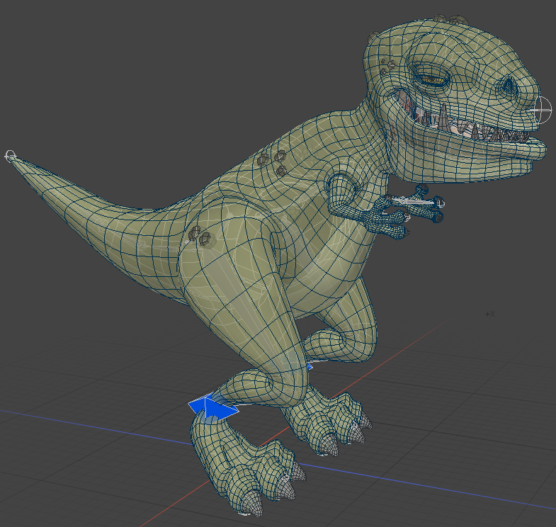
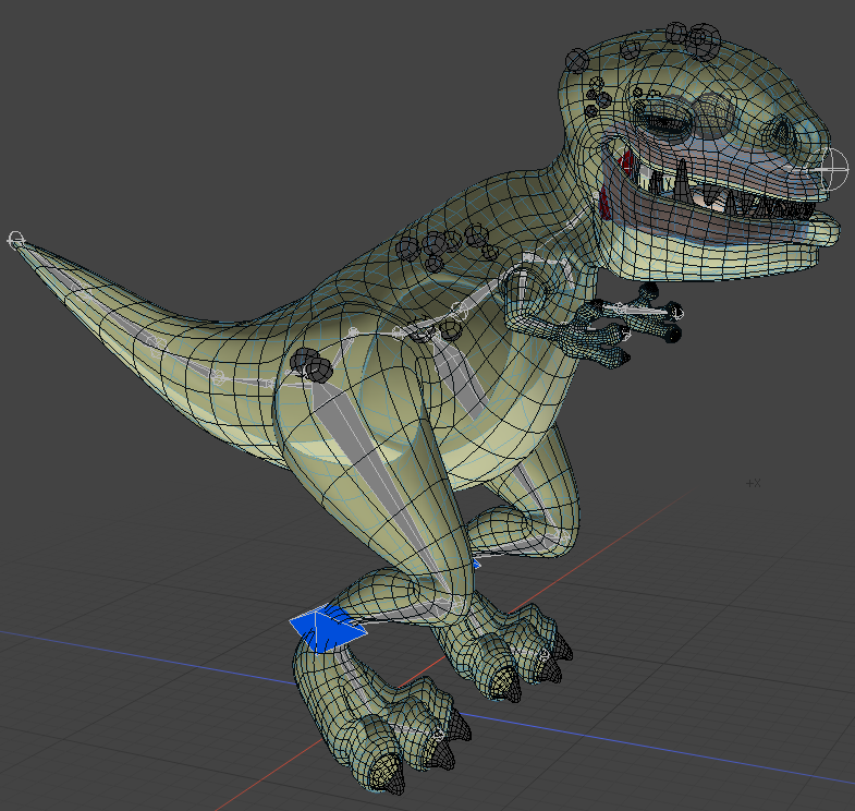
Topology Mode |
This option aids the process of retopologizing a mesh, sometimes also called simply topo. This is the process of converting a high resolution mesh to a low resolution mesh by creating new polygons against the high resolution mesh set as a background element. Generally, this process creates intersecting geometry that is difficult to see. Enabling the Topology Mode: This option forces the drawing of vertices and edges to always draw in front of background elements in the scene. Polygons are displayed as semi-transparent shapes with solid blue edges. Vertices are enlarged for easier visibility. |
|
Show Viewport Controls and Information |
This toggle controls the display of all the viewport element overlays, such as the axis widget, move, scale and Rotate tool's and the information overlays. When the controls are disabled, you can press O while hovering the mouse pointer over the target viewport to open the viewport options panel again. |
|
Show Camera Framing Region |
This option allows you to toggle the visibility of the camera framing regions in the 3D Viewport. Click the image below to view an animation.
|
|
Show Wireframe in Item Mode |
Toggle to enable wireframe drawing in Item mode, giving a cleaner display to differentiate between Item and Component modes. Note: Setting this option overrides the settings in the Active Mesh and Inactive Mesh tabs. For more information, see Active Meshes and 3D Viewport Properties. |
|
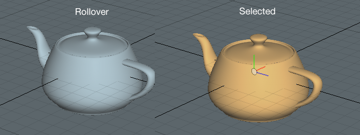
Selected Item Drawing |
Selected items are drawn as a wireframe (the default) with a transparent fill color over the mesh. The following options are available: • Wireframe - The selected items in the scene are displayed as a wireframe with a transparent fill color over the mesh. • Filled - The selected items in the scene are displayed with a transparent yellow mesh. Roll over an item in your scene to display the item in a transparent light blue mesh.
• None - The selected item in the scene is displayed in a fill color and the unselected items in the scene are drawn in wireframes. |
|
Replicators |
This option allows you to control the shaded display of any Replicator in a scene. You can adjust this setting to never (None), or always (All) display shaded Replicators, or only when a Replicator Item is active (Selected). Otherwise, the Replicator clones are displayed as bounding boxes. For more information, see Replicators. |
|
GL Background |
You can choose from several viewport-specific GL background options for controlling what is seen in the background of the viewport. • None - Displays no background, only the defined viewport color is visible. • Gradient - Displays a gray gradient shading that is multiplied over the viewport color. • Environment - Displays the settings as determined by the Environment Item of the Shader Tree, simulating the rendered output. • Image - You can define a custom image for use as a viewport background. When this option is selected, a file requester opens where you can select or navigate to the appropriate image. For best results, image should be a spherical projection. |
|
GL Reflection |
You can choose from several viewport-specific GL reflection options for controlling the display of reflective surfaces. • None - Displays no reflection, ignoring surface material settings. • Gradient - Displays a gray gradient shading on reflective surfaces. • Environment - Displays the settings as determined by the Environment item of the Shader Tree, simulating the rendered output. • Image - You can define a custom image for use as reflections (only applies to custom reflective surfaces, or Reflection viewport display mode. When this option is selected, a file requester opens, where you can select or navigate to the appropriate image. For best results, the image should be a spherical projection. • Same as GL Environment - Reflection options are determined by the GL Background settings. |
|
Camera Item |
In the case of multiple cameras in a scene, where the viewport is set to Camera view type, this option determines which camera item controls the viewport. Selecting alternate cameras changes the viewport to that camera's point of view. Note: Navigating in the viewport while in this mode physically moves the camera in the scene. |
|
Light Item |
In the case of multiple lights in a scene, where the viewport is set to Light view type, this option determines which light item controls the viewport. Selecting an alternate light changes the viewport to that light's point of view. |
Related Videos
Selected Item Drawing
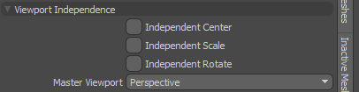
Viewport Independence
|
Independent Center/Scale/Rotate |
To make viewport navigation easy, it is sometimes desirable to link or unlink grouped 3D viewports, so when changing the position, size and angle of the viewport view, associated viewports move in sync with the active viewport. These three toggles allow you to control the syncing of the view properties center, scale, and rotate. |
|
Master Viewport |
Determines the linking of viewports, on a per viewport basis, using the Orthographic, which links all associated orthographic viewports, and Perspective, which links associated perspective views (does not include camera and light views). |
Background Imagery
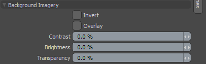
For scenes using Front type texture projection method in the environment item, either from a camera or light, the background imagery options control the display of the projected environment image in the viewport. To use it, apply an image to the Environment item in the Shader Tree, and in its associated Texture Locator, assign the Front projection type, and specify a camera or light if necessary. For more information on Texture Locators, see Texture Locator.
|
Invert |
Inverts the RGB values of the projected image. |
|
Overlay |
When enabled, draws the projected image on top of the viewport, obscuring its contents. When set as such, changing the Transparency allows you to see the viewports contents. |
|
Contrast |
Adjusts the contrast of the projected viewport image, modifying the visual difference between light and dark values in the image. Positive values increase the contrast, while negative values decrease it. |
|
Brightness |
Adjusts the brightness of the projected viewport image. Positive values brighten or lighten the image, while negative values darken it. |
|
Transparency |
Changes the opacity of the viewport projected image. When set to Overlay, it affects the visibility of items in the scene through the image. When overlay is disabled, this value reveals the settings of the background options. |
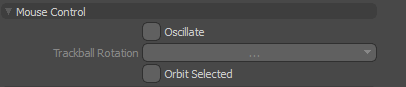
Mouse Controls
|
Oscillate |
In the Perspective view type, you can enable the Oscillate option. Then, using Alt+right-click , drag the cursor, moving the view. When you let go of the mouse button, Modo continues to bounce back and forth, oscillating over the previous mouse movement. This is useful when you want to view a model in motion. |
|
Trackball Rotation |
You have several options for orbiting behavior when navigating the viewport. When trackball rotation is disabled, viewport rotations are limited to two axes. When enabled, the viewport can be rotated on multiple axes based on the mouse's viewport position, as if the viewport itself was a giant trackball. The options are: • No - Disables trackball style rotation in favor of standard upright orbiting. • Yes - Enables trackball rotation for the specific viewport. • Default - Uses the preference setting available on Windows and Linux in System > Preferences > Input > Remapping > Viewport Rotation and on Mac OS in Menu > Preferences > Input > Remapping > Viewport Rotation. Note: Trackball rotation is disabled by default in the Preferences. |
|
Orbit Selected |
When this option is enabled, Modo automatically orbits around the selected element, using the selection's bounding box center as the center of rotation. |
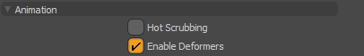
Animation
|
Hot Scrubbing |
When enabled, animated items in the scene update continuously when dragging the Timeline, producing a smooth motion. When disabled, items only update when the mouse pauses, or isn't moving, providing slightly faster performance. |
|
Enable Deformers |
This toggle allows viewports to display the results of animated morph and Vertex Map deformers in the viewport. By default, this option is enabled in all built-in 3D viewports. Note: When this option is disabled, mesh operations are not displayed in the viewport. |
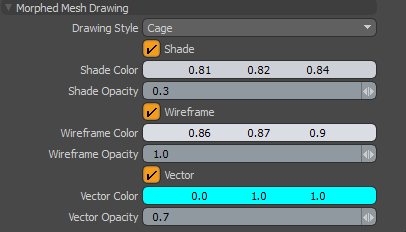
Morphed Mesh Drawing
|
Drawing Style |
Specify how you would like to draw Morph Maps. The following options are available: • Default - Modo draws the traditional morphed mesh. • Cage - Modo draws the base mesh and the morphed mesh as a cage. When this option is selected, additional properties are revealed: • Shade - Draws a transparent morphed mesh as a cage. • Shade Color - Specifies the color of the morph cage. Note, only displayed when a Shader, Wireframe, or Vector is enabled. • Shade Opacity- Specifies the opacity value of the morph cage. • Wireframe - Draws the cage in wireframe mode. • Wireframe Color - Specifies the color of the wireframe. • Vector - Draws line segments from the vertices of the base mesh to the corresponding vertices of the morph mesh. Note: To display a morphed mesh, you need to select a morph map with Enable Deformers disabled. • Vector Color - Specifies the color of the vector lines. • Vector Opacity - Specifies the opacity value of the vector lines. |
Visibility
Item Visibility
|
Show Lights |
Toggles the visibility of the light item representations in the current viewport. Typically disabled for modeling views. |
|
Light Illumination |
When Show Lights is enabled, disabling this control turns off illumination from all lights in the scene to improve viewport response times. This is especially useful if you have multiple lights in the scene that you want to adjust. You can still see the light widgets in the viewport, but the illumination they provide is disabled so you can move the light positions quickly and easily. |
|
Show Cameras |
Toggles the visibility of the camera item representations in the current viewport. Typically disabled for modeling views. |
| Show Locators | Toggles the visibility of the locator item representations in the current viewport. |
| Show Texture Locators | Toggles the visibility of the texture locator item representations in the current viewport. |
| Show Meshes | Toggles the visibility of Mesh Items in the current viewport. |
| Show Instances | Toggles the visibility of instance items in the current viewport. |
| Show Pivots/Centers |
Visibility for pivot and center representations can be determined by these criteria: • None - Only shows the pivot/center when in Pivots/Centers selection mode. • Selected - Shows the pivot/center when any item layer is selected in the Item List. • All - Always shows the pivot/center for all items. |
General Visibility
|
Show Work Plane |
Toggles the visibility of the Work Plane in the current viewport. (keyboard shortcut is Num Pad *). • Always - Set to always display the Work Plane. This is the default option. • Active - Set to display the Work Plane when it has been active. For example, moved or rotated. • Never - Set to never display the Work Plane. |
|
Show Grid |
Toggles the visibility of the ground plane grid at the 0 position of the up axis. • Always - Set to always display the grid. • Inactive Work Plane - Set the main grid to be drawn when the work plane is not active. This has the effect of there being only one grid drawn at a time. This is the default option. • Never - Set to never display the grid. |
|
Draw Faded Grid |
Toggles the visibility of the main grid and Work Plane to be drawn faded. |
|
Faded Grid Color Axes |
Toggles the visibility of the main grid and Work Plane to be drawn with colored axes. |
|
Show Backdrop |
Toggles the visibility of any Backdrop Image items in the scene. For more information on Backdrop Images, see Modeling with Images. |
Selection Visibility
|
Show Selections |
Toggles the visibility of selection highlighting. |
|
Show Selection Normals |
When enabled, this option displays normals for any selected polygon(s), displayed as a small dashed line pointing outward from the center of the polygon. Normals represent the facing direction for polygons. |
|
Show Selected Filling |
Toggles the visibility of the selection highlight overlay. |
| Show Selected Outline | Toggles the visibility of the selection highlighting outline. |
| Show Selection Rollovers | Toggles the visibility of selection rollover pre-highlighting. |
Performance
By disabling some of these options, the performance is improved in the 3D viewport when you are working with complex models.
|
Fur |
Toggles the visibility of fur material applied to your mesh. |
|
Displacements |
Toggles the visibility of Displacement maps. |
| Mesh Smoothing | Toggles the settings applied to smooth geometry. When enabled, polygons shade according to the material Smoothing setting. |
| Use Shader Tree | Toggles the materials and textures created in the Shader Tree. |
| Use Texture |
When enabled, all viewport textures, except displacements, are displayed in the viewport. |
HUD
|
Show Viewport HUD |
Toggles the visibility of the Tool HUD. Press Ctrl + Tab to toggle the HUD off and on. |
|
HUD Property Form |
Specifies what property form the Tool HUD uses. You can customize the property form in the Form Editor, available from the menu bar. Click System > Form Editor. In the editor, the available property forms are listed under Form HUD. |
|
HUD Style |
Specifies how the Tool HUD is displayed. The following options are available: • fixed - Sets the Tool HUD to a fixed position. • floating - Allows the Tool HUD to be moved around. • Close - Transforms the Tool HUD into a moveable palette with a Close button. |
|
Allow HUD Customization |
When enabled, you can add new tools to the Tool HUD and remove existing ones. When disabled, the set of tools in the Tool HUD can't be edited. |
Advanced Options
The Advanced Viewport options control the settings applied only to the Advanced viewport display style.
Effects
|
Ambient Intensity |
Adds an even illumination globally to all diffuse surfaces in a scene. This is especially useful for simulating additional bounces of light. |
||||||
|
Ambient Color |
Allows you to specify a color value for the global light added by the Ambient Intensity setting. Note: Ambient Intensity and Ambient Color are also available in the Render Items's Global Illumination settings. The Global Illumination settings are applied at render time, and override the viewport settings. |
||||||
|
Show Shadows |
Toggles the visibility of Direct Light shadows in the viewport. Note that Point, Directional, and Spot Lights generate more accurate shadows than Area and Cylinder lights. |
||||||
|
Shadows CSM |
Increases or decreases the shadow quality displayed in the viewport. You can set the number of shadow buffer projections the Cascade Shadow Map system uses for the light source to view casting curved shadows on curved surfaces. The following options are available: off, x2, x3, and x4. The higher the value specified, the smoother the shadow edges are. By default, this option is set to x2. Note: The higher the level specified, the more memory and processing time are required. (Lower values render faster but produce less shadow detail.) |
||||||
|
Shadows Resolution |
Sets the texture resolution used when depth projecting the shadows. The following options are available: Low, Mid, and High. By default, this option is set to High. |
||||||
|
Shadows Filter |
Sets whether the shadows are filtered. By default, this option is On. When working in a complex scene, turn this option off to improve performance in the 3D viewport. |
||||||
|
Use Normal Maps |
Toggles all normal map visibility. |
||||||
|
Use Bump Maps |
Toggles all bump map visibility. |
||||||
|
Materials |
Overrides the Shader Tree materials being used in the scene. This setting provides faster rendering performance results in the Advanced viewport when rendering a number of different types of materials. These options are also useful when working with a Unity Material or Unreal Material. • Simple - Produces a fast, simple rendering in the Advanced Viewport. Note, this option does not support Image Based Lighting or shadows. • Basic - Produces a rendering in the Advanced Viewport using simple traditional Shader model materials. Most basic Shader Tree materials are supported. For example, Diffuse and Specular materials. Unity Material, Unreal Material, Image Based Lighting, and shadows are also supported. In most cases, selecting this option produces faster results than selecting the Full option. • Full - Produces a full rendering, using all of your specified materials, that is similar to the output of the Preview Viewport and Render Display. This option takes more time to render. |
||||||
|
Groups |
Controls how Shader Tree groups are handled in the 3D viewport: • Flat - Ignores groups and produces a flattened Shader Tree. • Full - All Shader Tree groups are rendered. |
||||||
|
Lighting |
Sets the light sources that are used to illuminate the geometry. • Default Viewport - Uses normal viewport lighting. This includes scene lights, Image Based Lighting, and the default Viewport Light. • Scene - Uses only lights in the scene. This excludes the Viewport Light and Image Based Lighting. • Environment - Uses only the Environment image for lighting. • Scene + Environment - Combines both Scene and Environment lighting. • Default + Environment - Combines both Default Viewport lighting, including scene lights, Image Based Lighting, and the default Viewport Light with Environment lighting. This is the default setting. |
||||||
|
Background |
Selects the viewport background type: • Default Viewport - Uses the default background. • Environment - Draws the background as defined by the Environments settings in the Shader Tree. This allows you to show Environment detail that was previously only available in the Render Display. |
||||||
|
Display Override |
Sets the option to remove wireframe lines or widgets from the viewport: • (none) - Draw all lines and widgets. • Render without wireframe - Removes wireframes but draw widgets, and overlay information. • Render without wireframe and widgets - Removes wireframes, widgets and overlay information. |
||||||
|
Visibility |
Controls the visibility of items in the viewport when set to Advanced. When set as the Render option, the Render visibility setting on each item determines viewport visibility, and when set to the Viewport option, an item's visibility is determined by its Items list visibility (as controlled by the eye column of the Items list). |
||||||
|
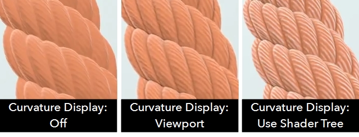
Curvature Mode |
Sets how the curvature shading is calculated when Curvature Display is set to Use Shader Tree or Viewport: • Fast - uses a derivative calculation to produce faster, lower quality shading. • Screen Space (Geometric) - uses a global screen space calculation based on the geometry to calculate shading, producing the curvature effect between each polygon, along each edge, making it easier to see how the geometry was constructed. • Screen Space (Normals) - uses a global screen space calculation based on the geometry normals to calculate shading, which smooths the curvature over the whole surface making it easier to see the curvature effect for larger, smoother shapes. |
||||||
|
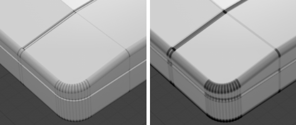
Curvature Display |
Controls how curvature shading is displayed in the viewport: • Use Shader Tree - use the Occlusion type selected in the Shader Tree to calculate curvature shading for each mesh. The example image shows Hard Light occlusion. Note: The Occlusion layer Type property must be set to Curvature to apply the selected occlusion type. • Viewport - use the Viewport to calculate curvature shading equally on the entire scene. • Off - no curvature shading is added. |
||||||
|
|
|||||||
|
Curvature Intensity |
Controls the intensity of curvature shading when Curvature Display is set to Use Shader Tree or Viewport. |
||||||
|
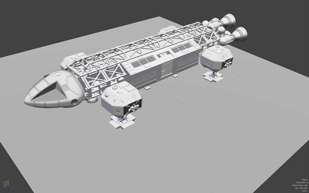
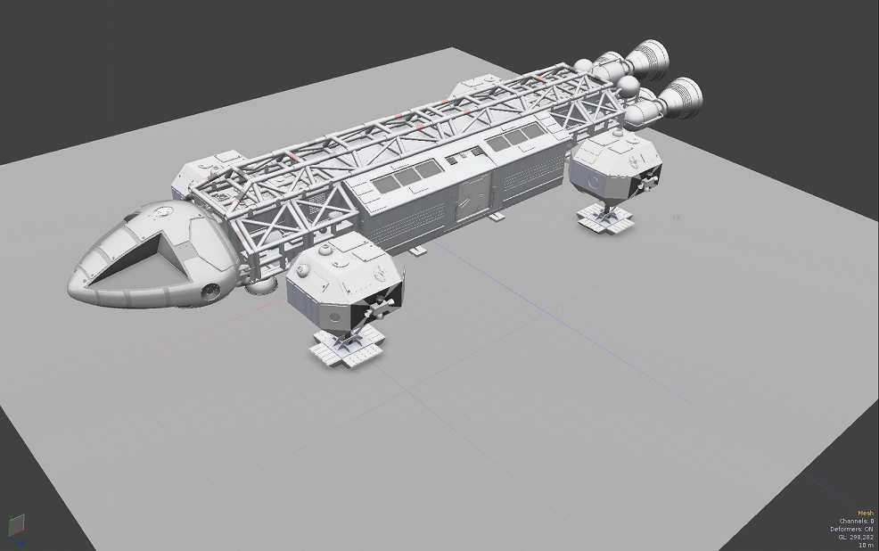
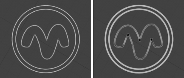
Ambient Occlusion Mode |
Sets the mode of rendering screen-space Ambient Occlusion, an effect that darkens recessed areas of a surface, producing a look similar to global illumination light scattering. You have the following options: • Off - The default option. Disables Ambient Occlusion in the Advanced viewport. • Hybrid - An improved, more robust version of the original Ambient Occlusion effect. It works better on large scale scenes than the original effect. Note: Click a thumbnail below to see the full-size image.
Note: This effect is completely independent of the Ambient Occlusion Shader Tree layer and not representative of how it renders, but adds an additional visualization possibility to enhance the look of the GL viewport models. In Hybrid mode, additional options become available to fine-tune the look of the Ambient Occlusion effect. • Radius - Determines the size of the effect. A large radius can affect performance. • Bias - Adjusts the shading falloff curve. Lower values darken the Ambient Occlusion, while higher values lighten the effect. This option is not used by Hybrid mode. • Intensity - Controls the overall strength (darkness) of the Ambient Occlusion effect. The higher the Intensity value, the darker the result. • Blur Radius - Applies a blur to soften the resulting Ambient Occlusion effect, producing a smoother overall result, but higher values, result in greater performance cost. |
||||||
|
Antialiasing |
Determines the amount of subsampling of viewport drawing that smooths the jagged display of the Advanced viewport. The default is set to Off. |
||||||
|
Multisampling |
With Antialiasing enabled, as you increase the Multisampling value, the amount of jaggedness reduces. The default is 1. |
||||||
|
Progressive |
Another way of producing anti-aliased images. It specifies the maximum number of frames used to produce the final image in the Advanced viewport. Specifying higher values results in anti-aliased images. When interacting with the viewport, it runs at full non-aliased frame rates, then improves the quality and aliasing over time when there's no interaction with the viewport. The default value is 1, which means the option is off. |
||||||
|
Line Antialiasing |
Renders an anti-aliased model wireframe displayed in the 3D viewport. The following options are available: • Off - No attempt is made to anti-alias the model wireframe rendering. This is always the fastest option. • System - If the present drivers support it, the 3D (OpenGL) viewport smooth line drawing is used. This is fast but has limited support. For more information on supported hardware, see the Release Notes. • Full - The 3D Viewport uses a special shader to render anti-aliased model wireframes. This is the slowest option but it provides the best visual quality. Note: The Line Antialiasing option is independent of the general Antialisaing option. Note: On macOS (especially ARM hardware) using the Full option can yield significantly lower performance. |
||||||
|
Anisotropic Filtering |
Filters all material textures using the Graphics Processing Unit (GPU) value. The Max level is different for all GPUs. When enabled, the GPUs hardware texture filters units to apply the best Anisotropic filtering the GPU can do. The default value is set to Off. |
||||||
|
Transparency |
Defines the display of transparent surfaces. The following options are available: • Off - Disables transparency drawing. • Fast - Does simple depth sorted transparency. • Correct - Does correct depth sorted transparency, producing a more accurate result. Use the Mode and Depth dropdowns to control how Correct Transparency is calculated. |
||||||
|
Correct Transparency Mode |
Sets how Modo sorts layers of transparency to render the final image: • Depth Peeling - uses the legacy Modo method to sort transparency. The results from Depth Peeling may not be as high quality as Full mode. Note: Depth Peeling is the only mode available on macOS, Shallow and Full are unsupported. • Shallow - only sort the top number of layers specified by the Correct Transparency Depth control, resulting in faster rendering of transparency. • Full - sort all layers of transparency, which produces the best result at a cost of processing time. |
||||||
|
Correct Transparency Depth |
When Correct Transparency Mode is set to Shallow, sets the number of layers of transparency to sort. |
||||||
|
Screen Space Reflections |
Shows surface reflections as you would in the Render Display. The reflection can be adjusted by adjusting the material properties, namely Reflection Amount, Reflection Type, Blurry Reflection and Roughness. See Material for more details. • Off - Disables reflections. • Fast - Enables fast (non-blurry) reflections. • Blurry - Enables full reflections with blur. Note: The frame rate will get worse with an increase in the number of reflected objects, especially if they are blurred. |
||||||
|
Dither Mode |
The advanced viewport has the following options for controlling color processing. • Off - Disables dithering, which may reveal banding in the image. • Ordered - Introduces simple ordered dither to reduce banding caused by color gradients. This option is enabled by default. • HDR - When using a HDR/XDR monitor, image intensity can go into High Dynamic Range. Note: The HDR option is currently only available on MacOS 10.15 or higher. |
||||||
|
ColorSpace Mode |
Use this setting to change the color space displayed in your viewport. • OCIO - Uses the colorspace loaded into Modo's global OCIO profiles. See Custom OCIO profiles for more information. • sRGB - Enabled by default. Sets the colorspace to sRGB, which is commonly used by computer displays. • Linear - Applies a linear calculation to pixel color and brightness values rather than a gamma curve. May improve performance slightly. |
Active Meshes
The following options allow you to control the display of elements that are in the foreground, meaning they are selected in the Items list. Background layers are those that are visible, but not selected.
Shading
|
Shading Style |
You can choose from the available view styles covered above: Wireframe, Solid, Shaded, Vertex Map, Texture, Shaded Texture, Default, Advanced, Gooch, Cel and Reflection Shading |
|
Wireframe Overlay |
Determines the style of geometry wireframe display. You can adjust the colors of the wireframe using the preference setting in Windows in System > Preferences > Display > Colors and on Mac OS in Menu > Preferences > Display > Colors. Once a color scheme is created in the Preferences and saved as a named preset, it must be applied to the active viewport with the menu bar command View > Viewport Color Scheme. • None - No wireframe displayed. (/) • Uniform - By default this is a white wireframe outline. (Shift+/) • Colored - By default this is a black wireframe outline. (Ctrl+/) |
|
Wireframe Opacity |
Controls the opacity of the wireframe overlay display. |
|
Wireframe Color |
Specifies the color of the wireframe in the 3D viewport. |
|
Vertex Map |
Defines which type of Vertex Map is displayed when in the Vertex Map viewport. • Selection - Displays the most recent Vertex Map selection. • Weight - Favors Weight Maps for display. • Vertex Color - Favors vertex color maps for display. |
|
Smooth Shade |
This toggle overrides the material Smoothing setting, only changing how smoothing is displayed in the viewport, not the rendered output. When disabled, individual polygons shade flat, appearing faceted. When enabled, polygons shade according to the material Smoothing setting. |
|
Show Weightmaps |
When enabled, selected Weight Maps are visible as overlays to the shaded elements in the 3D viewport in Default viewport display style. This includes the automatic weights associated with bones and deformers. |
|
Show PSUB Masks |
Toggles the visibility of the sculpting masks in the viewport when working with multi-resolution sculpting. When a masks visibility is disabled, the mask still affects the target unless the Enable Mask option is inactive. For more information, see Using Sculpting Masks. |
| Show UV Boundaries | Toggles visibility of UV boundaries in the 3D viewport. These display as thin purple lines overlaid on the surface, representing the outline of each UV island. The default color can be changed in the System > Preferences > Color options. |
| Show Geometry Boundaries | Toggles visibility of Geometry boundaries. These display as a thin green line on any open edges of a surface. Especially useful in highlighting hidden surface discontinuities. |
| Show UV Distortion |
Toggles visibility of the colors displayed for the geometry with signifying distorted areas. Enabling this option displays a color overlay on the geometry, fading toward red when polygons are distorted and smaller (relative to other polygons in the map) and fading toward blue when they are distorted and larger (relative to other polygons). Polygons that are the closest relative size to others in the map with the least distortion display a middle gray/green color.
|
| Show Locked Mesh Items | Displays locked polygons, edges, and vertices in the 3D viewport in a specified color. This option is enabled by default. For more information, see Locking. |
Display
|
Vertex Map Display |
Sets which color component of the selected RGBA map is drawn in the Vertex map mode. The following options are available: • RGB • Alpha • Red • Green • Blue Note: The Shading > Shading Style must be set to Vertex Map to set the Vertex Map display. |
|
Independent Point Size |
This is a per-viewport override for the display size of selected vertices. When enabled, you can specify the actual display size with the Point Size option. |
|
Point Size |
Determines the display size of selected vertices when the Independent Point Size option is enabled. Values are in screen pixels. |
|
Show Vertices |
Allows you to set visibility in the selected 3D viewport. The following options are available: • Always - Always show vertices. • In Component Modes - Only show vertices in Component mode. • In Vertex Mode - Only show vertices in Vertex Component mode. • Never - Never show vertices. |
|
Edge Thickness |
Controls the thickness of edges on active meshes. Increasing the default value of 1.0 can help you see edges more easily at different zoom levels. |
|
|
|
|
Curve Thickness |
Controls the thickness of active curves. Increasing the default value of 1.0 can help you see curves more easily at different zoom levels. |
|
|
|
|
Show Cages |
Toggles the visibility of the Subdivision Surface Cage representation. This can be considered the original polygons that were smoothed. |
|
Show Guides |
Toggles the visibility of guide lines that draw between the subdivision limit surface and the cage geometry. |
|
Show Indices |
Toggles the visibility of the component index values display. Each number represents the particular component index. Visibility can be especially helpful when working with Geometry Constraints, where Constraints require specific index values for input. |
|
Show Weight Values |
Toggles the visibility of Weight Map value display. A numeric value representing the current vertex weight amount displays next to each selected vertex in the 3D viewport. See Working with Vertex Maps for Weight Map usage information. |
|
Enable Independent Drawing |
The Display Viewport allows you to define custom display options for each item layer. By default, the Enable Independent Drawing option is enabled and these custom drawing options display in all viewports. When enabled, all custom drawing options are ignored for active meshes. |
Transparency Overrides
|
Transparency Mode |
Allows you to differentiate between background and foreground wireframes, so you can easily understand the topology you're working with. This option is especially useful for decluttering heavy wireframe models. The following options are available:
Note: Transparency overrides are not available in Wireframe mode. If you want to use transparency overrides on inactive meshes, make sure that their shading style is NOT set to Wireframe under 3D Viewport Properties > Inactive Meshes > Shading > Shading Style. |
||||||||||||
|
Polygon Color (front) |
Specifies the color of front-facing polygons in Ghost or Xray mode. |
||||||||||||
|
Polygon Opacity (front) |
Specifies the opacity value of front-facing polygons in Ghost mode. |
||||||||||||
|
Wireframe Color (front) |
Specifies the color of front-facing wireframes in Ghost or Xray mode. |
||||||||||||
|
Polygon Color (back) |
Specifies the color value of back-facing polygons in Ghost or Xray mode. |
||||||||||||
|
Polygon Opacity (back) |
Specifies the opacity value of back-facing polygons in Ghost or Xray mode. |
||||||||||||
|
Wireframe Color (back) |
Specifies the color of back-facing wireframes in Ghost or Xray mode. |
||||||||||||
|
Wireframe Opacity (back) |
Specifies the opacity value of the wireframe in Ghost or Xray mode. |
||||||||||||
|
Overlay |
When enabled, the visible front faces of the mesh are overlaid on top of everything else. |
||||||||||||
|
Link Wire Opacity |
When enable, the front wireframe opacity is linked to the back wireframe opacity so that the two can be controlled together. |
||||||||||||
|
Flat Shaded |
When enabled, meshes are rendered with self illumination and without lighting effects. |
||||||||||||
Inactive Meshes
The following options allow you to control the display of item layers that are in the background, meaning that they are visible in the Items list, but unselected (not highlighted).
Overrides
|
Make Inactive Same as Active |
When enabled, this option overrides all settings of the Inactive Meshes options panel and all background item layers display as foreground elements. |
|
Make Inactive Invisible |
When enabled, all item layers that are visible according to the visibility column of the Items list, but unselected don't show in the 3D viewport. This makes it easy to solo a single layer by simply selecting it without affecting the rendered image or requiring multiple layers' visibility to be toggled. |
Shading
|
Shading Style |
You can choose from the available view styles covered above: Wireframe, Solid, Shaded, Vertex Map, Texture, Shaded Texture, Default, Advanced, Gooch, Cel and Reflection Shading. |
|
Wireframe Overlay |
Determines the style of geometry wireframe display. You can adjust the colors of the wireframe using the preference setting on Windows and Linux in System >Preferences > Display > Colors and on Mac OS in Menu >Preferences > Display > Colors. Once a color scheme is created in the preferences and saved as a named preset, it must be applied to the active viewport with the menu bar command View > Viewport Color Scheme. • None - No wireframe displayed. (/) • Uniform - By default this is a white wireframe outline. (Shift+/) • Colored - By default this is a black wireframe outline. (Ctrl+/) |
|
Wireframe Opacity |
Controls the opacity of the wireframe overlay display. |
|
Wireframe Color |
Defines which color to display. |
|
Vertex Map |
Defines which type of Vertex Map is displayed when in the Vertex Map viewport. • Selection - Displays the most recent Vertex Map selection. • Weight - Favors Weight Maps for display. • Vertex Color - Favors vertex color maps for display. |
|
Smooth Shade |
This toggle overrides the material Smoothing setting, only changing how smoothing is displayed in the viewport, not the rendered output. When disabled, individual polygons shade flat, appearing faceted. When enabled, polygons shade according to the material Smoothing setting. |
|
Show Weightmaps |
When enabled, selected Weight Maps are visible as overlays to the shaded elements in the 3D viewport in Default viewport display style. This includes the automatic weights associated to bones and deformers. |
|
Show PSUB Masks |
Toggles the visibility of the sculpting masks in the viewport when working with multi-resolution sculpting. When a masks visibility is disabled, the mask still affects the target unless the Enable Mask option is inactive. For more information, see Using Sculpting Masks. |
|
Show UV Boundaries |
Toggles visibility of UV boundaries in the 3D viewport. These display as thin purple lines overlaid on the surface, representing the outline of each UV island. The default color can be changed in the Color Preferences section. |
|
Show Geometry Boundaries |
Toggles visibility of Geometry boundaries, These display as a thin green line on any open edges of a surface. Especially useful in highlighting hidden surface discontinuities. |
|
Show UV Distortion |
Toggles visibility of the colors displayed for the geometry with signifying distorted areas. Enabling this option displays a color overlay on the geometry, fading toward red when polygons are distorted and smaller (relative to other polygons in the map) and fading toward blue when they are distorted and larger (relative to other polygons). Polygons that are the closest relative size to others in the map with the least distortion display a middle gray/green color.
|
|
Apply Current Morph |
When a Morph Map is selected, the Morph is applied to all visible meshes, in active layers and inactive layers. The Apply Current Morph option toggles the display of Morphs for background (inactive) layers. |
Display
|
Independent Point Size |
This is a per-viewport override for the display size of selected vertices. When enabled, you can specify the actual display size with the Point Size option. |
|
Point Size |
Determines the display size of selected vertices when the Independent Point Size option is enabled. Values are in screen pixels. |
|
Show Vertices |
Toggles the visibility of unselected vertices (selected vertices are always visible, unless Show Selection is disabled). |
|
Edge Thickness |
Controls the thickness of edges on inactive meshes. Increasing the default value of 1.0 can help you see edges more easily at different zoom levels. |
|
|
|
|
Curve Thickness |
Controls the thickness of inactive curves. Increasing the default value of 1.0 can help you see curves more easily at different zoom levels. |
|
|
|
|
Show Cages |
Toggles the visibility of the Subdivision Surface Cage representation. This can be considered the original polygons that were smoothed. |
|
Show Guides |
Toggles the visibility of guide lines that draw between the subdivision limit surface and the cage geometry. |
|
Enable Independent Drawing |
The Display viewport allows you to define custom display options per item layer. By default, these custom drawing options display in all viewports. However, when the Enable Independent Drawing option is enabled, all custom drawing options are ignored for active meshes. |
Transparency Overrides
|
Transparency Mode |
Allows you to differentiate between background and foreground wireframes, so you can easily understand the topology you're working with. This option is especially useful for decluttering heavy wireframe models. The following options are available:
Note: Transparency overrides are not available in Wireframe mode. If you want to use transparency overrides on inactive meshes, make sure that their shading style is NOT set to Wireframe under 3D Viewport Properties > Inactive Meshes > Shading > Shading Style. |
||||||||||||
|
Polygon Color (front) |
Specifies the color of front-facing polygons in Ghost or Xray mode. |
||||||||||||
|
Polygon Opacity (front) |
Specifies the opacity value of front-facing polygons in Ghost mode. |
||||||||||||
|
Wireframe Color (front) |
Specifies the color of front-facing wireframes in Ghost or Xray mode. |
||||||||||||
|
Polygon Color (back) |
Specifies the color value of back-facing polygons in Ghost or Xray mode. |
||||||||||||
|
Polygon Opacity (back) |
Specifies the opacity value of back-facing polygons in Ghost or Xray mode. |
||||||||||||
|
Wireframe Color (back) |
Specifies the color of back-facing wireframes in Ghost or Xray mode. |
||||||||||||
|
Wireframe Opacity (back) |
Specifies the opacity value of the wireframe in Ghost or Xray mode. |
||||||||||||
|
Overlay |
When enabled, the visible front faces of the mesh are overlaid on top of everything else. |
||||||||||||
|
Link Wire Opacity |
When enable, the front wireframe opacity is linked to the back wireframe opacity so that the two can be controlled together. |
||||||||||||
|
Flat Shaded |
When enabled, meshes are rendered with self illumination and without lighting effects. |
||||||||||||