3D (OpenGL) Viewport
The 3D viewport is the most frequently used interface in Modo. It is the window into Modo's virtual 3D world. It serves many purposes, allowing you to sculpt, paint, animate, deform, move elements about, and position cameras and lights. With so many jobs to do, it's important that it be flexible as well. There are numerous functions within the 3D viewport that allow you to customize what is seen and how it is seen, depending on the task at hand.
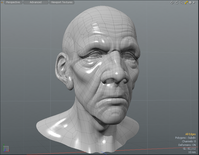
When Modo is opened for the first time, it opens to the default Model layout with a large 3D viewport set to Perspective view. When examining the viewport, you see a dark grid moving in perspective off into the distance some, with another coarser light colored grid perpendicular to the dark one.
Grid Displays
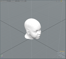
The dark grid represents the ground plane, the zero position of the Y (or Up) axis. Each square of that grid represents a fixed distance. Since this grid is dynamic depending on the zoom level, a small display in the lower right corner gives you the real world equivalent measurements for each square unit, in the case above it is 50mm.
The lighter grid represents Using the Work Plane, which is also dynamic depending on your rotational orientation to the world. While the ground plane is purely for reference purposes, the Work Plane's purpose is to show you where objects get created in the 3D space. Think of it as a construction plane, dynamically adjusting to the most appropriate angle.
Tip: Right mouse click over any Item in the 3D Viewport and select Set Work Plane from the contextual menu to align the work plane to the item center.
Also within the 3D viewport, there are text and information overlays that give you pertinent information with regards to items visible within the viewport as well as guides to selections and the currently selected tool. All of these work together, providing important feedback to speed and enhance the overall workflow.
Additional Controls
To get the most of the 3D views, there are also many additional controls you can directly access when necessary. In the upper left corner of the window is a small circle, called the Thumb. Next to it, there are three capsule shaped buttons. The Thumb is dark gray until a viewport becomes active in which case it turns orange. To make any viewport active, simply click anywhere within the window frame. Right-clicking on the Thumb presents you with a series of options regarding the frame. See Using Layout Controls for further details regarding the options.

The left-most capsule button next to the Thumb is for choosing the way the viewport sees the scene (see Tool HUD). Click on it to open a pop-up menu that allows you to choose from the available options of Perspective and various isometric views, or viewing the scene from the Camera or Lights point of view or Ray GL options giving you a fast, fully rendered in-viewport representation of the scene. The Viewport Textures icon allows you to quickly select Environments, Matcaps, and UV Textures to display in the 3D Viewport without having to add them to the Shader Tree. For more information, see Viewport Textures.
The upper right corner has several small icons. The first three let you manipulate the view itself, move, rotate and adjust the zoom level of the active viewport. Clicking and dragging over any of the icons makes the appropriate view adjustment providing an intuitive way for manipulating the position of the viewport's virtual camera. For easier and faster viewport navigation, see Navigation. The next one is the Minimize/Maximize arrow. Click to expand the active viewport to fill the entire local frame, allowing for additional viewport space to manipulate the contents. When the arrow is yellow, click it to minimize the viewport and reveal the other associated viewports.
The gear contains all the available viewport customization control options. Here you can change how the geometry is represented in the viewport, control wireframe overlays and change how items in the background are displayed (items that are visible, but unselected are considered background elements), as well as set the visibility of many individual viewport elements. These options can also be accessed by hovering the mouse pointer over the target window and pressing O on the keyboard. For more information on viewport customization, see below.
The tiny arrow icon to the right, is called the Widget. For more information on this control, see Using Layout Controls. Right-click to open a pop-up menu that allows you to select one of the Modo viewports. Selecting any of these items converts that window into the chosen viewport.
Note: Don't select anything unless you mean to change it, as viewport changes cannot be undone. See Customizing Your Layout for more information regarding viewport customization (and how to get back the default interface when you need to).

On the lower left of the viewport, there is an XYZ axis gizmo that provides a visual reference to the orientation of the window as well as the current work plane orientation. For orthographic views, the icon displays the axis plane the viewport windows faces toward. In perspective view, you can rotate the view and see the widget update in real time. The lower right corner has several informational text displays that dynamically update, showing the current number of selected items, channels and deformers. The GL display references the number of live polygons active in your viewport (including Sub-D surfaces) and the number at the bottom gives the real world size reference to the squares within the grid of the ground plane. The specific information displayed is controlled in the GL section of the Display Preferences.
Navigation
Modo provides a number of functions to aid in the navigation of GL viewport allowing you to navigate in 3D space in various ways. Most are mouse button and keyboard combinations. Shortcuts are based on the default interface values. For additional navigation options, see Remapping in Input Preferences.
|
Keystroke(s) |
Action |
|---|---|
|
Alt+left-click |
Rotates view
|
|
Alt+middle-click |
Rotates viewport Z axis (bank) view |
|
Alt+right-click |
Flick Rotate (also called Free Wheeling) view slows down when mouse is released. |
|
Shift+Alt+left-click |
Pans View
|
|
Shift+Alt+right-click |
Up/Down Pan only |
|
Ctrl+Alt+left-click |
Zooms to mouse position |
|
Ctrl+Alt+right-click |
Box Zoom (drag box to zoom) |
|
. (period) |
Zooms In |
|
, (comma) |
Zooms Out |
|
G |
Centers view (Current mouse position to viewport center)
|
|
/ |
Turns (Spinning view of scene) |
|
Shift+/ |
Turns upright |
|
Mouse Wheel Scroll |
Zooms view in & out to mouse pointer |
|
A |
Fits (Zoom to scene extents/all Items) |
|
Shift+A |
Fits selected (Zooms to selected elements) |
|
Ctrl+A |
Aligns selected (Aligns view to current selection) |
|
Ctrl+Shift+A |
Fits and aligns selected (Zooms and aligns view to current selection) |
|
Ctrl+ Spacebar |
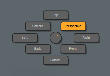
Displays a pie menu. Hover your cursor over any of the options and release to select a view.
|
Visibility
Modo provides a way to modify the visibility of object in the viewport directly. While generally you can toggle visibility of items in the Items List that changes visibility of the entire layer. The following commands allow the temporary toggling of visibility of only the selected element, including components, depending on the selection mode. Once hidden, geometry becomes uneditable. To hide a piece of geometry, select the geometry component you wish to hide and in the menu bar, go to View > Hide Selected or press H on the keyboard. To make the geometry visible again, click View > Unhide or press the U key.
Note: When a file is saved and re-opened later, all hidden polygons are visible.
|
Keystroke(s) |
Action |
|---|---|
|
H |
Hides selected geometry (hides all if nothing is selected). |
|
Shift+H |
Hides unselected geometry. |
|
Ctrl+H |
Hides invert (toggles visibility, inverting the present state). |
|
U |
Makes all hidden geometry visible for the currently selected layers. |
Locking
Providing a similar function to hiding, locking allows you to fix a selection of geometry so that it is not editable, however it is still visible.
Courtesy William Vaughan
To lock item layers:
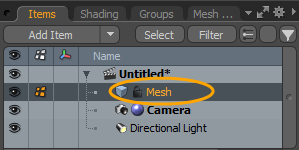
| 1. | On the right panel, open the Items List, and right-click the item you want to lock. |
| 2. | Select Lock/Unlock from the dropdown menu. |
A lock icon appears on the mesh item in the Items list.
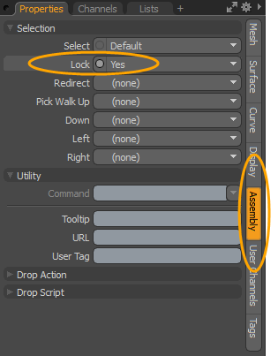
• Alternatively, in the Properties tab of the selected mesh item, open the Assembly tab, and set Lock to Yes. For more information, see Assembly Viewport.
You can unlock a locked element by right-clicking on the item and selecting Lock/Unlock. The lock icon is removed when unlocked.
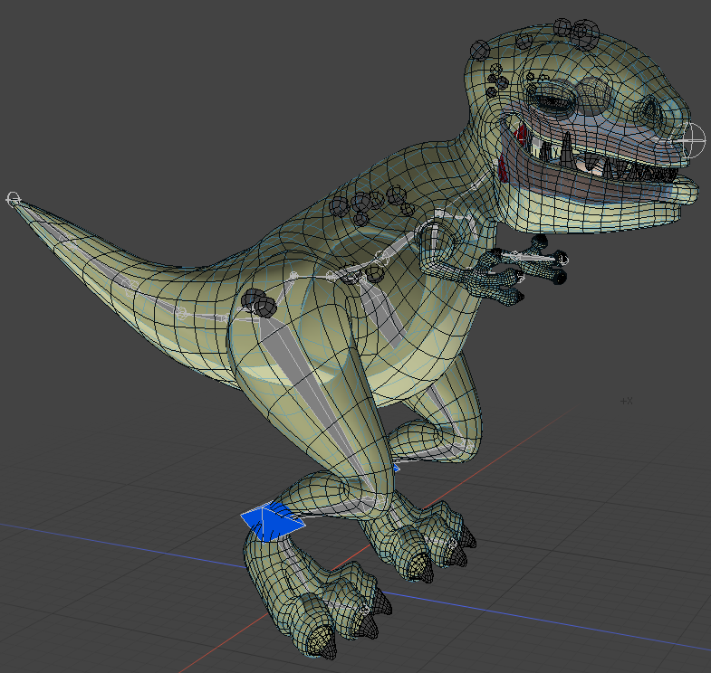
While working in the 3D viewport, you can lock selected components to assist you in your workflow. Modo displays locked polygons, vertices, and edges with a specific color in the 3D viewport.
Note: In edge selection mode, Modo also displays locked vertices since the locked edge elements are associated with vertex or polygon elements.
To lock a component selection of geometry in the 3D viewport:
| 3. | In the 3D viewport, select the geometry you wish to lock using one of the selection modes (Vertices, Edges, Polygons, or Items). |
For more information about selecting geometry, see Selecting Items.
| 4. | In the menu bar, click Edit > Lock Selected or press J. |
Tip: You can unlock any locked elements in the 3D viewport by clicking Edit > Unlock or by pressing I.
|
Lock Key Shortcuts |
Action |
|---|---|
|
J |
Locks selected geometry (locks all if nothing is selected). |
|
Shift+J |
Locks unselected geometry. |
|
Ctrl+J |
Locks invert (toggles locked state of all geometry). |
|
I |
Makes all locked geometry editable. |
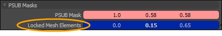
To change the color of locked elements:
| 1. | In the menu bar, click System > Preferences, expand Display, and click Colors. |
| 2. | Under PSUB Masks, set the Locked Mesh Elements color by clicking-and-dragging the values in the field or click on the field to open the Color Picker to select your color. For more information, see Color Picker Viewport. |
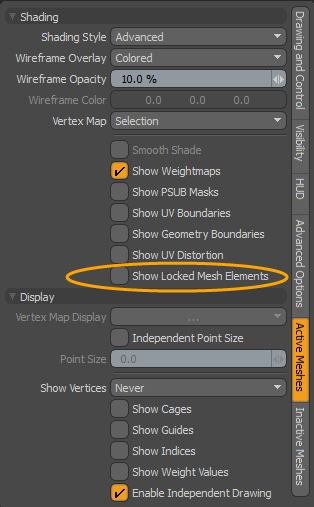
To disable Show Locked Mesh Items:
By default, Modo displays locked mesh items in the viewport. You can disable this in the viewport properties.
| 1. | In the top-right corner of the 3D viewport, click the gear icon to display the properties. |
![]()
| 2. | Open the Active Meshes tab, expand the Shading section, and uncheck Show Locked Mesh Items. |
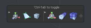
Tool HUD
The Tool HUD is available in every layout of the 3D viewport. It is a context-sensitive form containing the most recent tools for each layout. It also displays different sets of tools depending on the active selection mode.
To enable the Tool HUD press Ctrl/Cmd+Tab on the keyboard.
When you first open the Tool HUD , it displays a set of custom tools for the particular layout and selection mode. As you keep using various tools, they are added to the Tool HUD's most recent tools section on the left.
When you click a tool in the Tool HUD, the tool becomes active and its icon is highlighted in orange until you drop it.
You can add new tools to the Tool HUD by activating the tool, then clicking the + button on the right.
To remove a tool, click x in the upper-right corner of the tool's icon in the Tool HUD.

You can customize the Tool HUD in the 3D Viewport Properties, in the HUD sub-tab. For more information, see 3D Viewport Properties.
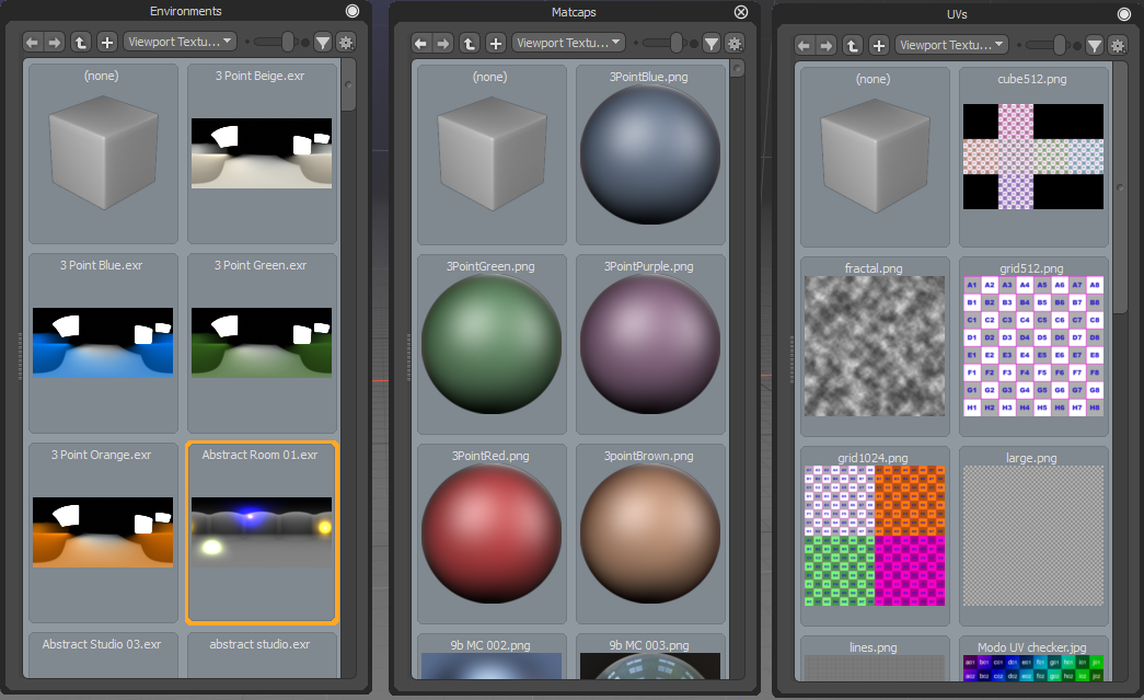
Viewport Textures
Predefined textures can be applied to your scene to quickly see a preview in the 3D Viewport using any of the 3D Viewport Styles. A variety of environments, MatCaps shaders, and UV textures are available. When you double-click on a texture, your scene is updated in the 3D Viewport without having to add any items in the Shader Tree. Using this feature enables you to experiment with different textures before actually creating Shader Tree layers. For more information, see Shader Tree Item Layers.
Note: Items that you have set in the Shader Tree are not overwritten. To view your set Shader Tree items, click Render > Open Preview and click the arrow to render your scene.
The following options are available:
|
Option |
Description |
|
Environments |
When an environment texture is set, Modo replaces the Environment item in the Shader Tree. |
|
Matcaps |
When a MatCap shader is set, Modo completely replaces the surface shader used in the Shader Tree with the selected MatCap shader. |
|
UV Textures |
When a UV texture is set, Modo replaces the Diffuse texture applied on the mesh surface and uses a default material. A number of provided UV Textures are used for UV Diagnostics. Note: When applying UV Textures to a Preset mesh, the UV Map name for the UV Texture must be the same as the UV Map name used by the Preset. |
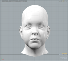
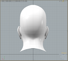
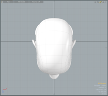
View Types
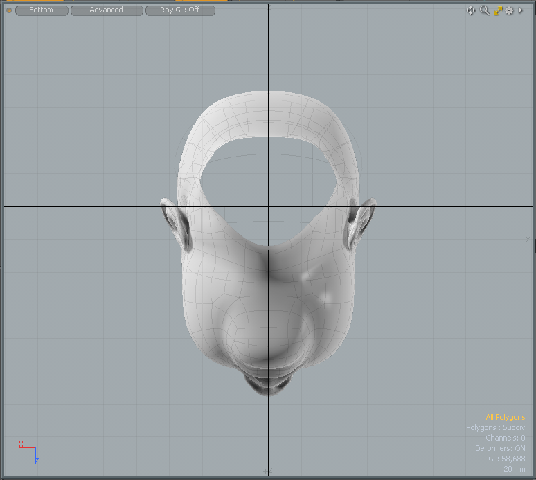
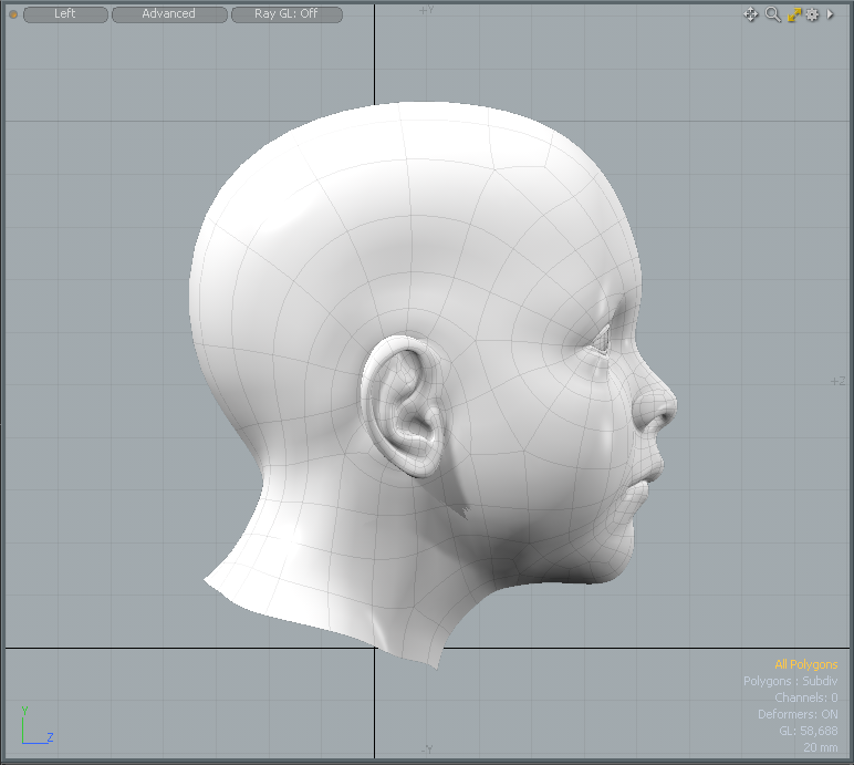
While viewports have no actual camera, Modo does provide you the ability to change how a scene is viewed through the viewports. The options can be selected from the View Type menu in the upper left corner of the viewport. Click on the button to open the menu where you can choose alternate options. The following orthogonal views provide viewpoints free from perspective distortion of all the cardinal viewing planes -front, back, top, bottom, left and right.
|
|
|
|
|
Front |
Back |
Top |
|
|
|
|
|
Bottom |
Left |
Right |
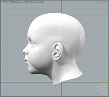
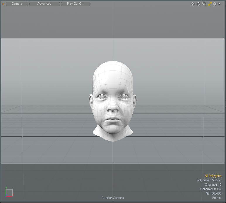
Perspective views are similar to viewing the scene through a real-world camera, where the displays have perspective and a vanishing point. The amount of perspective distortion can be controlled in the menu bar, on Windows, in System > Preferences > Display > OpenGL setting Flatness of Perspective and on Mac OS, Menu > Preferences > Display > OpenGL setting Flatness of Perspectivein (This is for the Perspective view only, the Camera and Light views are controlled by the item's settings). Additionally, you can view a scene from the Camera's point-of-view, mimicking the field of view settings of the item. When in the Camera mode, translucent black bars appear over the frame to represent the rendered frames aspect ratio, for when it doesn't match that of the viewport frame. Finally, there is also the Light view that displays the scene from a particular light's point-of-view, providing an easy way to see what the light is pointed at and illuminating.
Note: When navigating in the Camera or Light views, you are actually moving the positions of the elements within the scene.
|
|
|
|
|
Perspective |
Camera |
Light |
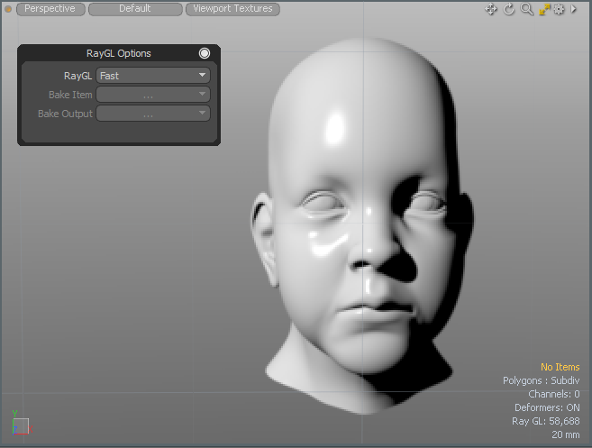
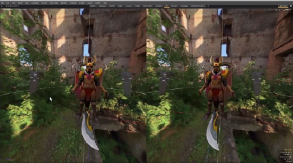
Ray GL
The Ray GL viewport option leverages Modo's render preview functionality overlaid with the standard viewport options to provide a hybrid display of the rendered scenes, where you can model and interact with the rendered scene directly. To use it, click the center button on the top left of the 3D viewport and select Ray GL.
There are three options to choose from:
• Full - Nearly approaches the quality level of a final render but with a reduced ray amount for faster interaction.
• Fast - Forgoes textures for a speedier preview of the scene.
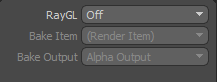
• Bake - Provides a preview of a bake. When selected, choose from the following options:
• Bake Item - Select the bake item to use for the bake:
- (Render Item) - Bake via the Render Items.
- (Current Bake Item)- The currently selected bake item.
- One of the other bake items in the scene.
• Bake Output - Choose from one of the available outputs for the currently selected bake item. Outputs can be render outputs or texture outputs from a bake item. Texture outputs are based on the selected texture effect.
For more information see Working with Bake Items and Baking Tools
For simpler scenes, shading is near real-time, just like in the render preview, but for more complex scenes, there is a lag between edits, where the system temporarily reverts back to the standard GL view. Users can control how Ray GL updates based on options available within the RayGL Preferences available on Windows in System > Preferences > Display > Ray GL and , on Mac OS in Menu > Preferences > Display > Ray GL. Additionally, you can choose which elements are taken into account when rendering. For example this can be useful when you want to disable fur rendering to speed up the preview when modeling an object with complex fur.
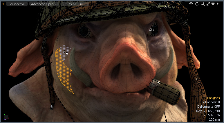
Model courtesy of John Hayes
3D Viewport Styles
Modo provides a number of ways to visualize a scene using viewport styles. These are in-viewport shaders that display the geometry in specific ways, making it easier to visualize certain aspects of a model or scene. You can choose from the available options by using the Viewport Options button within the viewport (the second button from the left on the top).
|
Layout |
Description |
|---|---|
|
|
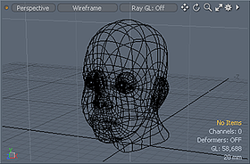
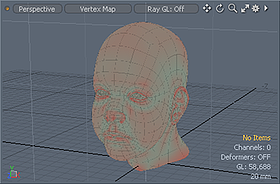
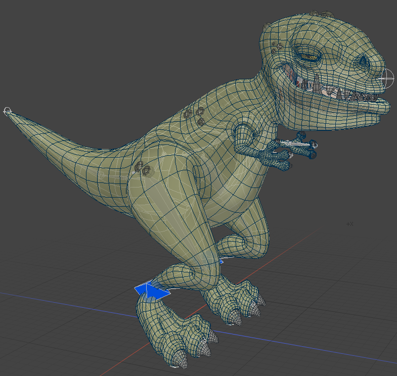
In the Wireframe drawing style only vertices and the edges that connect them to make polygons are visible. The actual polygon faces are not drawn, and as such, you can see through the model to vertices and polygon edges on the backside as well. |
|
|
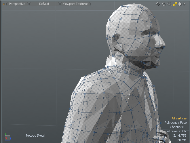
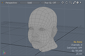
The Solid shading mode renders the geometry without shading. This mode is most useful when combined with a wireframe overlay, resulting in a flat rendered sketch mode. |
|
|
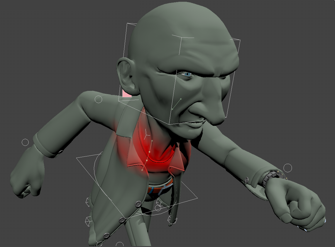
The Vertex Map shade option uses the currently selected Vertex Map to shade the model. In the case of Vertex Color maps, the color of each vertex is blended with the colors of the neighbor vertices. For Weight Maps, positive values shade red while negative values shade blue. Any vertex with a value of 0 or no value at all is shaded green. If Color and Weight type Vertex Maps are selected, the Color Vertex Map takes precedence. |
|
|
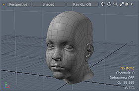
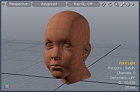
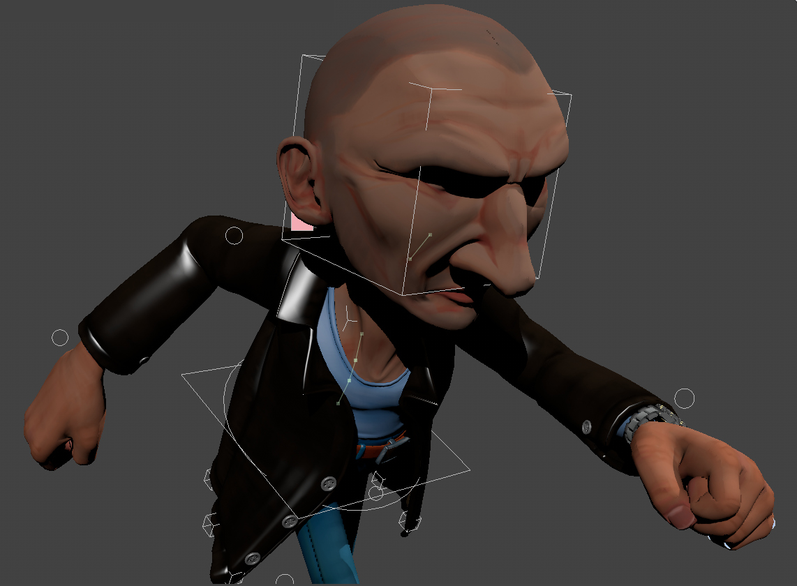
The Shaded style shows meshes with their basic material definitions such as Diffuse, Specular and Transparency. No image maps appear in the Shaded style. |
|
|
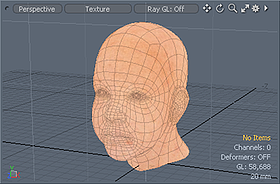
The Texture style shows the mesh surface with only the most basic material attributes including any image map textures. In Texture style, RGBA images can be seen with their alpha blending them into the material beneath. However, limitations of standard Open GL force the image map to draw without shading (that is, full bright). This is a reasonable view style for 3D painting or placing image decals onto a model. The Shaded Texture style can shade the image texture but cannot use alpha channel. The Advanced view correctly alpha blends multiple image texture layers and shades them appropriately. |
|
|
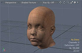
In the Shaded Texture view, image maps are visible as blended with the light shading effects. Due to OpenGL limitations this mode cannot show images with alpha channels, so any RGBA image appears as an opaque RGB image. To see alpha channels from the image, use the Texture, Default or Advanced view styles. |
|
|
The Default view allows you to see many more effects than the normal Texture view. With Default mode you can see the following types of image maps: Color, Bump, Specular, Luminous and Transparency. It blends multiple layers of each (though Bump only uses the first layer). However, the total number you actually see at a time is based on the resources of your graphics card. These resource limitations are per Shader Tree surface so if your card has 8 texture units, each Material can have up to 8 image maps. Aside from simple alpha blending, each layer's opacity is respected as well as the base material settings - so you can, for instance, set the material to be 50% transparent, then create a clip and apply it as a transparency map and paint in areas of complete transparency or complete opacity (previously referred to as Advanced GL). |
|
|
The Advanced viewport provides a more powerful rendering mechanism by using modern graphics technology. The purpose of this viewport is to be able to produce closer results to the final offline render of scenes, within an interactive manner. Supporting more functionality than the 'Default' view, the Advanced viewport supports reflections and fresnel of the Physical Shader, fur materials, as well as 'Ambient Occlusion' and Direct Light shadows and has its own viewport antialiasing. These functions, and more, can be enabled and controlled in the Viewport options panel (see Advanced Options). A graphics card with at least OpenGL 3.2 support is required for Advanced Viewport, and the VBO mode must be enabled. When activated, toggle buttons are displayed in the 3D viewport allowing you to select a shading mode. Select one for the following: Note: Group Masks are supported in the Advanced 3D viewport, allowing you to work on complicated material setups directly in the viewport and to make changes in real time. There is little difference between the representation of a material in the Advanced 3D viewport and the representation of a material in Modo’s Preview Viewport. |
|
|
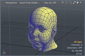
The Gooch shading mode is a vertex shading algorithm that displays the geometry using a technique known as tone shading. Rather than relying on the traditional light to dark shadow style shading, which can obscure parts of the model while working, tone mapping represents the curvature of the geometry, shading warm-to-cool where the warm areas are those that would traditionally be lit and the cool areas are those that would normally be in shadow. This shading mode allows you to check the surface of your model for proper contouring while still seeing the entire mesh evenly lit. |
|
|
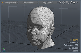
The Cel Shading style creates a stepped shading on the model to appear as if it were a cartoon with a fixed number of shading zones. |
|
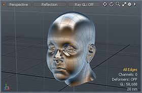
The Reflection shader displays your geometry as if it were fully reflective. This shader uses a cubic reflection map, and mixes in some of the original material properties with a small amount of shading to properly show object contours. This mode is very useful when performing visual review of a models surface as it assists in finding surface irregularities. |
|
The RayGL shader leverages Modo's render preview functionality overlaid with the standard viewport options to provide a hybrid display of the rendered scenes, where you can model and interact with the rendered scene directly. |
|
|
The Fusion Profile shader leverages Modo's MeshFusion functionality. |
|
|
The HMD quality presets provide a high quality image display. Select one of the presets, High, Low, Mid, or Ultra, for better performance in the HMD. Tip: If you are experiencing visual performance issues, select a lower HMD quality preset. For more information, see Options, Scenes, and Performance. |
|
The Model Base returns back to the default Model layout after selecting a previous viewport style. |
|
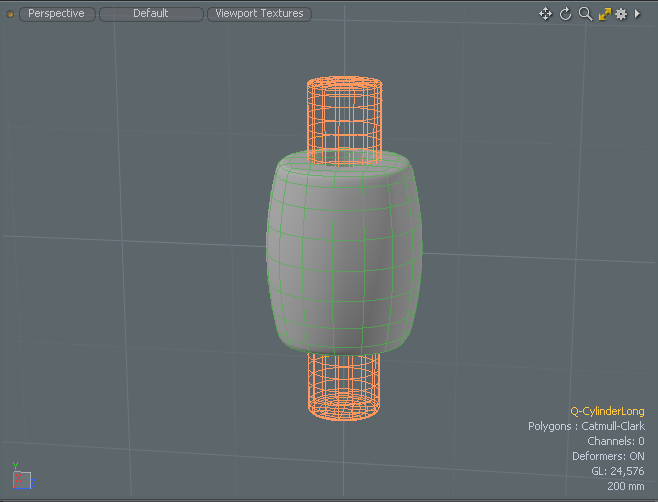
The MeshFusion Shader leverages Modo's MeshFusion functionality to display meshes drawn in wireframe: the primary mesh is green, and the trim is magenta. They are color-coded in the Item List as well. |
|
The Topology Shader displays the Topology preset in the 3D viewport. You can activate this when using the Model layout. |
|
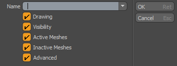
Save Viewport Preset allows you to save the 3D view as a preset and to specify if Drawing, Visibility, Active Meshes, Inactive Meshes and Advanced viewport options are included. Once done, this viewport is listed in the 3D Viewport Styles dropdown menu. |
|
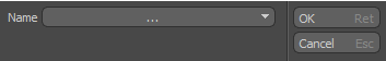
Delete Preset allows you to select a viewport preset to delete. |
Related Videos
Rendering AVP
Viewport Toggle Buttons
![]()
Use any of the following toggle buttons to quickly enable common options while working on your scene.
|
|
Viewport Textures |
Applies a predefined texture to your scene to quickly see a preview in the 3D Viewport using any of the 3D Viewport Styles. A variety of environments, MatCaps shaders, and UV textures are available. For more information, see Viewport Textures. |
||||||||||||
|
|
Replicators |
Sets how the replicators are displayed in the 3D viewport. The following options are available: • None - Draws all replicators as a bounding box. Choose this option for best performance. • Selected - Displays shaded replicators for only those selected. • All - Shades all replicators in the 3D viewport. |
||||||||||||
|
|
Show Weightmaps |
Displays the selected weight map on the geometry in the 3D viewport. If this option is enabled, weightmaps can be displayed in the Vertex Map viewport, the Default viewport and the Advanced viewport.
|
||||||||||||
|
|
Show UV Distortion |
Displays the UV distortion on the geometry in the 3D viewport. Note: A UV map must be selected to be visible in the 3D viewport. |
||||||||||||
|
|
Reference Item |
Aligns the coordinate system to the selected item. |
||||||||||||
|
|
Show Locators |
Toggles the visibility of the locator items in the 3D viewport. |
||||||||||||
|
|
Overlay Drawing |
Toggles the visibility of locator items through objects. |
||||||||||||
|
|
Make Inactive Invisible |
Hides inactive layers in the 3D viewport. |
||||||||||||
|
|
Make Inactive the same as Active |
Draws the inactive layers in the same styles as the active layers. |
||||||||||||
|
|
Transparency Overrides |
Allows you to differentiate between background and foreground wireframes, so you can easily understand the topology you're working with. This option is especially useful for decluttering heavy wireframe models. Clicking any of the options sets the override for active meshes. Alt+clicking an option sets the override for inactive meshes. The following options are available:
Note: Transparency overrides are not available in Wireframe mode. If you want to use transparency overrides on inactive meshes, make sure that their shading style is NOT set to Wireframe under 3D Viewport Properties > Inactive Meshes > Shading > Shading Style.
You can edit the Transparency Override properties, such as opacity values and wireframe color, for active and inactive meshes in the 3D Viewport Properties under Active Meshes > Transparency Overrides, and Inactive Meshes > Transparency Overrides, respectively. For more information, see 3D Viewport Properties. |
||||||||||||

Advanced Viewport Toggle Buttons
When the Advanced viewport style is enabled, the following toggle buttons are displayed in the 3D viewport.
|
|
Displays the basic geometry shading and materials. Use this shading mode for basic modeling. |
|
|
|
Displays basic shading, materials, shadows, and IBL lighting. Use this shading mode to balance speed performance and quality. |
|
|
|
Displays the highest quality shading and materials. Use this mode when working on textures and final render Playblast. Note: The complexity of the Shader Tree setup may affect performance. For example, if you have several layers under the parent shader item, it may take longer to display. |
Viewport Light
You can adjust the default lighting in a 3D viewport using the options found under View > Edit Viewport Lights. Once the function is active, you can click and drag in the viewport to change the current light's position. Additional properties are available in the Tool Properties for Color and Intensity. Current defines the particular light being edited. There are two lights by default. You can use the commands View > Add Viewport Light and View > Remove Viewport Light to modify the number of lights visible.
Viewport Presets
Under the viewport Styles menu there is an option to save a viewport Preset allowing you to capture all the current viewport settings and easily recall them at a later time. When the command is invoked, the following panel opens up.
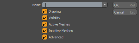
In the Name input field you specify a title for the Preset. This is the name that appears in the menu once saved for later recall. The option toggles represent the various options as defined in the associated viewport Options panel (covered below), allowing you to control specifically which setting is recalled with the saved preset. Directly under the Save Preset option is an additional command allowing you to delete any user-created viewport preset.
Contextual Menus
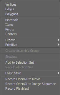
By right-clicking in the 3D Viewport in an empty scene, you are shown a contextual menu to assist you in your design workflow. As you select items that you have added to your scene, you can right-click on an item to view a contextual menu to display another set of related tools for your use. The following is an example of the contextual menu presented in an empty scene.
|
Option |
Description |
|
Vertices |
Change the selection mode to Vertices. |
|
Edges |
Change the selection mode to Edges. |
|
Polygons |
Change the selection mode to Polygons. |
|
Materials |
Change the selection mode to Material selection. |
|
Items |
Change the selection mode to Items. |
|
Pivots |
Change the selection mode to Pivots. |
|
Centers |
Change the selection mode to Centers. |
|
Create |
Create Backdrop Images, Camera Items, Locator Item, Mesh Item, and a number of other Modeling Operations. |
|
Primitive |
Add a number of Adding Primitives to your scene. |
|
Create Assembly Group |
Create an Assembly Group. For more information, see Assembly Inputs and Outputs |
|
Shaders |
Assign an image-specific Shader. |
|
Add to Selection Set |
Add the selected elements to a Selection Set. For more information, see Using Selection Sets. |
|
Recall Selection Set |
Recall any existing selection set. For more information, see Using Selection Sets. |
|
Lasso Style |
Change the Lasso style to Lasso, Rectangle, Circle or Ellipse. For more information, see Lasso. |
|
Record OpenGL to Movie |
Save your scene as a movie file. A number of file formats are available. |
|
Record OpenGL to Image Sequence |
Save your Image Sequence. A number of file formats are available. |
|
Record Playblast |
Set Playblast settings. For more information, see Playblast. |