Pack UVs
The Pack UVs tool automates the process of organizing UV island data to fit into the desired UV space. (A UV island is a connected group of polygons in a UV map.) It could be thought of as an automated puzzle solver. With the default settings, the tool moves, scales, and rotates each individual UV island until they all fit neatly within the designated grid space, as if solving a complex jigsaw puzzle.
Activating the Pack UVs Tool
Direct Modeling Tool:
• From the menu bar, click Texture > UV Operators > Pack....
• Using the UV layout, on the left panel, under Align and Pack, click Pack...
• With the UV palette open, under Align and Pack, click Pack...
![]()
Procedural Modeling Tool:
• In the Mesh Ops tab, click Add Operator, and double-click Mesh Operations > UV > Pack UVs.
• In the Schematic view, click Add..., and double-click Mesh Operations > UV > Pack UVs.
Applying the Direct Modeling Pack UVs Tool
The Pack UVs tool modifies the currently-selected UV map.
Note: If you have selected multiple UV maps, the first one selected is used to apply the Pack UV tool. Other selected UV maps are not affected.
For more information about how to create UV maps, see Create UV Tool.
Once your mesh is prepared, follow these steps:
Tip: You can also use the meshes available in Modo's Preset Browser. For more information, see Preset Browser.
| 1. | In the menu bar, click Layout > Layouts > UV to open the UV layout. |
Tip: You can save this layout to be easily accessible from the switcher bar by clicking the + button in the switcher bar. In the New Layout dialog, name your layout and check As Copy of Current Layout.
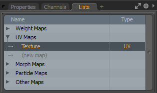
| 2. | Select a texture map. There are a number of ways to do this: |
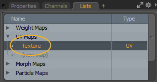
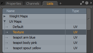
• On the bottom of the right panel, open the Lists tab, expand UV Maps, and select it from the list. It's called Texture by default.
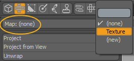
• On the left panel, set Map: (none) to the texture map.
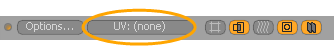
• On the UV viewport, click on the UV button, and select the texture map from the dropdown menu.
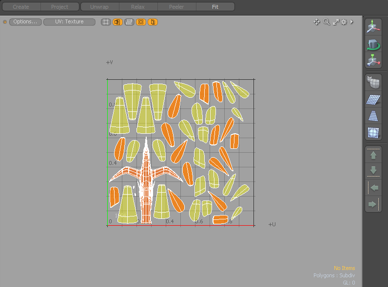
The UV viewport displays the UV map.
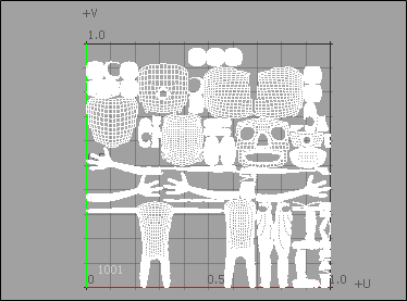
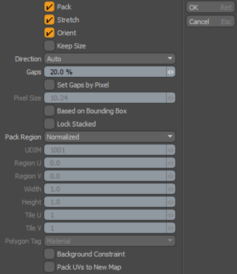
| 3. | On the left panel, under Align and Pack, click Pack.... |
| 4. | On the Pack UVs dialog, click OK. |
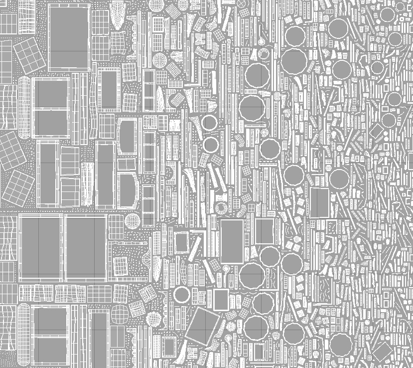
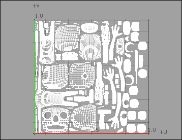
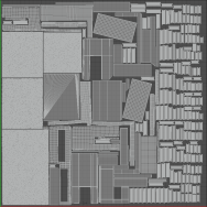
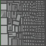
Each individual UV island fits neatly within the designated grid space
Creating UV Island Groups Based on Polygon Tags
You can create individual UV islands and texture maps for each applied polygon tag on a mesh. The following example uses the teapot primitive which has multiple materials (polygon tags) applied to it, and includes a UV map.
Tip: For more information about how to create your own UV maps, see Create UV Tool.
Tip: For information on using polygon tags, see Polygon Set Material/Part/Smoothing.
| 1. | With your model ready, in the menu bar, click Layout > Layouts > UV to open the UV layout. |
If you don't have a mesh, you can download our example scenes and use Teapot_example-polygons_tags.lxo.
| 2. | On the left panel, set Map: (none) to Texture. |
| 3. | On the left panel, under Align and Pack, click Pack... |
| 4. | In the Pack UVs dialog, set Pack Region to Polygon Tag, and click OK. |
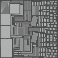
Each polygon tag is packed into separate UV islands and grouped by same polygon tag.
You can pack each polygon tag into separate UV maps by enabling the Pack UVs to New Map option. It retains the original UV map and names the separate UV maps based on the material name. These UV maps are listed on the right panel in the Lists tab under UV Maps. Clicking on each individual UV map displays it in the UV viewport.
Splitting One UV Island with Multiple Polygon Tags
You can split a UV map which has only one UV island into individual UV maps based on applied polygon tags.
If you don't have a mesh, you can download our example scenes and use sphere-two_materials-one_uv_island.lxo.
| 1. | In the UV layout, click Map (none) and select Texture. |
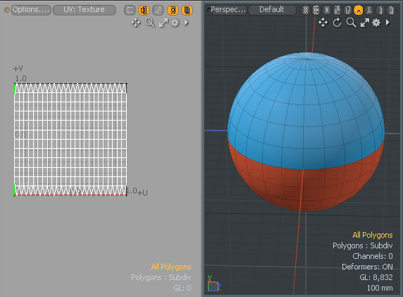
One UV island displays in the UV viewport.
| 2. | On the left panel, under Align and Pack, click Pack... |
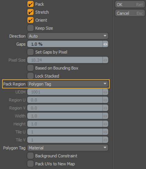
| 3. | In the Pack UVs dialog, set Pack Region to Polygon Tag and click OK. |
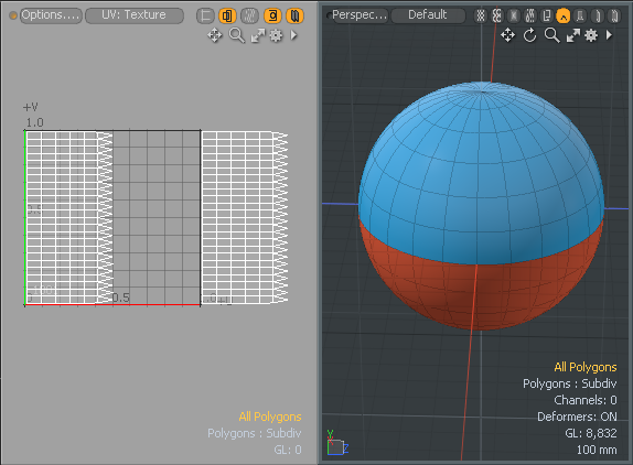
Two individual UV maps are created.
Tip: If you want the UV islands to retain their original size, enable Keep Size in the Properties tab. Enabling Keep Size disables the effect of Stretch.
Procedural Modeling Pack UVs Example
The Pack UVs mesh operation generates procedural UVs and organizes UV island data to fit into the desired UV space. This is particularly useful when you want to reorganize overlapping UV island data for a number of mesh layers, all containing their own UV maps, with a stack of mesh operations applied to your scene. Applying the Pack UVs operation easily reorganizes the data for you.
In the following example we set up simple procedural primitives in a scene, each having their own procedural UV maps. Once done, we'll apply a Merge Meshes operation to create one mesh item using all the primitive UV maps. As a result, you will notice how these UV maps overlap and the data is displayed in red in the UV viewport. To resolve the overlapping of UVs, we will apply our procedural Pack UVs tool to unpack the UV maps.
For more information, see Working with UV Maps.
To add procedural primitives:
| 1. | Open the UV layout. |
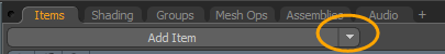
| 2. | On the right panel, click the down arrow beside Add Item, and click Mesh. |
| 3. | On the right panel, open the Mesh Ops tab, click Add Operator, and double-click Mesh Operations > Create > Primitives > Cube. |
Tip: If the Mesh Ops tab is not visible on the right panel, click the More Tabs or New Tab icon and select Data Lists > Mesh Ops.

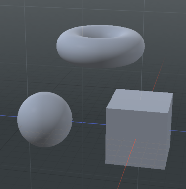
| 4. | In the 3D viewport, click-and-drag the move handles to position the primitive. |
| 5. | In the Items list, double-click on the mesh item you just created and type Cube. |
| 6. | With the cube mesh item selected, click Add Operator, and double-click Mesh Operations > UV > Create UV Map. |
| 7. | In the properties, set Projection Type to Atlas. |
| 8. | Repeat these steps to add an Ellipsoid and a Toroid procedural mesh item with UV maps. |
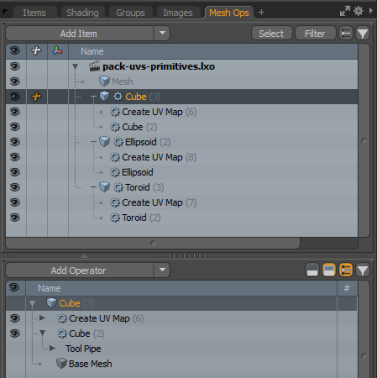
The Mesh Ops list displays the three primitives, each with their own UV map.
To apply a Merge Meshes operation:
| 1. | Select the first mesh item in the Items list. |

| 2. | Click Add Operator and double-click Mesh Operations > Edit > Merge Meshes. |
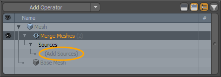
| 3. | Expand the Merge Meshes operator, and under Sources click (Add Sources). |
| 4. | Navigate to Modifier Mesh Operations > Existing and select the parent source mesh items. In this example, double-click Cube, and repeat for Ellipsoid, and Toroid. |
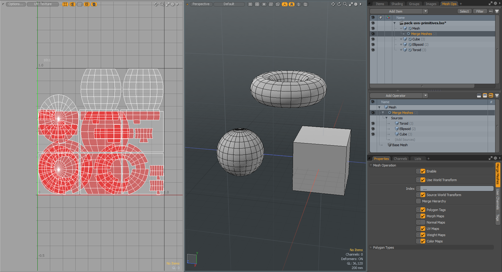
The three procedural primitives are listed under the Merge Meshes > Sources item.
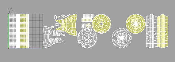
| 5. | On the bottom of the right panel, open the Lists tab, expand UV Maps, and select Texture. |
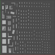
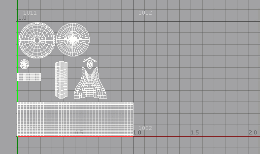
Notice how the UV data from the three UV maps is overlapping and displayed in red in the UV viewport.
To add a Pack UV:
| 1. | With the Merge Meshes mesh operation selected in the right panel, click Add Operator and double-click Mesh Operations > UV > Pack UVs. |
| 2. | In the Mesh Ops list, click the |
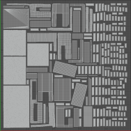
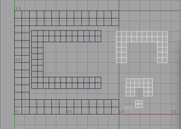
The UV data is reorganized in the UV viewport.
Tip: If you want the UV islands to retain their original size, enable Keep Size in the Properties tab. Enabling Keep Size disables the effect of Stretch.
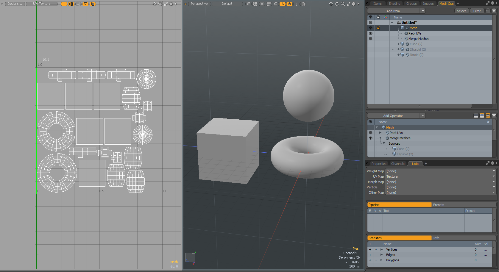
| 3. | With Pack UVs operation selected and the Properties tab open, set the Gaps value to 0.3%. |
The UV Island data is updated in the UV viewport.
Schematic Pack UVs Example
| 1. | Open the Setup layout from the menu bar, under Layout > Layouts > Setup. |
At the bottom of the Setup layout, the Schematic viewport is displayed.
| 2. | On the top left corner of the interface, click the |
![]()
| 3. | Select an asset to use. This example uses Cloud Assets > Meshes > Character > mhy3d bird. |
A Raven_ item is displayed in the Items list on the right panel.
| 4. | On the right panel, from the Items list, drag-and-drop this item into the Schematic viewport on the bottom of the Setup layout. |
| 5. | In the Schematic viewport, click Add..., and click Mesh Operations > UV > Create UV Map. |
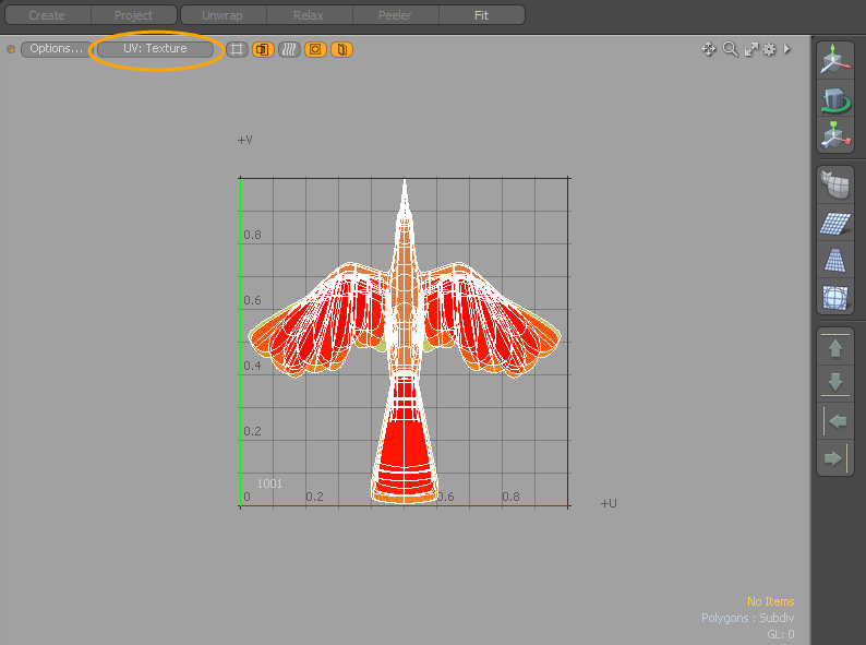
| 6. | From the main menu, click Texture > Open UV Editor and set the UV button to Texture. |
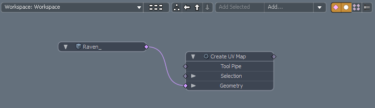
| 7. | On the bottom panel, in the Schematic viewport, click Add..., and double-click Mesh Operations > UV > Pack UVs. |
The Schematic viewport now displays the Pack UVs node.
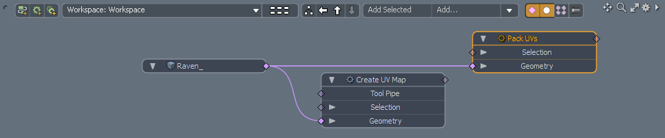
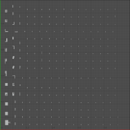
The UV Editor updates the UV island data. The Pack UVs operation reorganized the UV island data.
| 8. | In the Schematic viewport, select the Pack UV node, and update the properties in the right panel. |
Tip: If you want the UV islands to retain their original size, enable Keep Size in the Properties tab. Enabling Keep Size disables the effect of Stretch.
For more information, see Pack UVs Properties.
Pack UVs Properties
|
|
|
|
UV Pack tool properties |
UV Pack procedural properties |
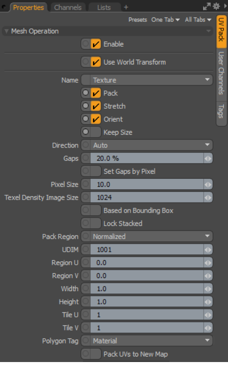
| Enable |
Toggles the tool off and on. This option is only available for the procedural Pack UVs mesh operation. |
||||||||||||
| Use World Transform |
When enabled, the mesh operation maintains the world space on the input layer. This option is only available for the procedural Pack UVs mesh operation. |
||||||||||||
| Name |
Specifies the UV map name. You can easily change it by clicking within the field and typing the new name. This option is only available for the procedural Pack UVs mesh operation. |
||||||||||||
| Pack | Controls whether the UV islands can be moved from their current location. | ||||||||||||
| Stretch | Scales and reshapes each UV island to decrease distortions within the UV polygon area/3D polygon area before packing. | ||||||||||||
| Orient | Controls whether the UV islands can be rotated as they are packed. | ||||||||||||
|
Keep Size |
When enabled, the original size of the UV islands is retained. Note: Enabling Keep Size disables the effect of the Stretch option. |
||||||||||||
| Direction |
Provides options for controlling the main orientation of the UV islands. • Auto orients them in the direction that best fits. • Horizontal orients UV islands in a mostly wide proportion. • Vertical orients them in a mostly tall proportion. |
||||||||||||
| Gaps |
Controls the final spacing between the islands. Greater values increases the spacing between neighboring UV islands.
|
||||||||||||
| Set Gaps by Pixel |
When enabled, Pixel Size is used instead of the Gaps attribute. The Gaps by Pixel value is automatically calculated using the following equation: Gaps = Pixel Size / Texel Density Image Size. |
||||||||||||
|
|
|||||||||||||
|
Pixel Size |
This option defines the gap size in pixel size based on the Texel Density Image Size.
|
||||||||||||
|
Texel Density Image Size |
The size of the image that is used for the Texel Density to be mapped to. A Texel Density Image Size of 512 represents a Texel Density of 512 pixels per UV unit.
For more information on Texel Density, refer to the Texel Density documentation. Note: When using the direct modeling version of the Pack UVs command, the Texel Density Image Size can be adjusted from the Image Size option in the Texel Density panel on the UV Tab. This option is only available for a procedural modeling mesh operation. |
||||||||||||
| Based on Bounding Box | When enabled, treats each island as a rectangular shape, based on the overall width and height. | ||||||||||||
| Lock Stacked | When enabled, keeps stacked islands intact when packing. Overlapping islands must share vertex positions, such as when UV mapped geometry is copied, pasted, and moved in the 3D viewport, or half of a model is mirrored for symmetry. | ||||||||||||
| Pack Region |
• Defines the location within the UV space to position the packed UVs. • Normalized - Packs UVs into the base 0 to 1 region. • Nearest - Packs UVs into the closest UV region based on its initial location. • UDIM - Allows you to define a specific UDIM region. When selected, the specific UDIM is specified in the input field below. Tip: UDIM is an automatic UV offset system that assigns an image onto a specific UV tile, which allows you to use multiple lower resolution texture maps for neighboring surfaces, producing a higher resolution result without having to resort to using a single, ultra high-resolution image. For more information, see UDIM Workflow. • Manual - Allows you to manually designate a UV space region as a packing area. When selected, the region is specified using the Region and Width/Height input fields below. • Tiles - Defines a maximum rectangular area by number of full regions wide and high, defined with the Tile U and Tile V values. This targets the packing to fill all the tiled sections within the defined region (without crossing the tile boundaries). • Polygon Tag - Groups UV islands by a polygon tag type to separate UDIM spaces. When enabled, you can specify the Material, Part, Smoothing Group, or Selection Set option to apply it to. • By Item - Packs UVs by mesh item when multiple mesh items are selected, and writes the result into separated UDIM spaces. When Pack UVs to New Map is enabled, the new map is named based on the name of the mesh item. |
||||||||||||
| UDIM | When the Pack Region option is set to UDIM, this option allows you to designate the specific UDIM region as the target for packing the UVs into. | ||||||||||||
| Region U/V and Width/Height |
When the Pack Region option is set as Manual, the Region and Width/Height values designate the target area for packing the UVs into. The Region U/V values define the lower-left corner of the packing region and the Width and Height values define the portion of that area that is used for packing, originating from the defined region position. For example, to fill all of the standard 0-1 UV space, the region would be set to 0,0 and the Width/Height would be set to 1.0, 1.0. If the region is set to -1,-1 and the Width/Height were set as 2.0, 2.0 then the UVs would fill the entire -1 to 1 on both axes, treating it as one giant UV area to pack into. |
||||||||||||
| Tile U/Tile V | Defines the rectangular tile region by U (width) and V (height) when using the Pack Region's Tiles option. | ||||||||||||
| Polygon Tag |
• Groups UV islands by a polygon tag type to separate UDIM spaces. The following options are available: • Material - Uses the Polygon Set Material tags applied to the mesh item. It packs each polygon tag into a separate UDIM and updates the original texture UV map. • Part - Uses the Polygon Set Part tags applied to the mesh item. • Smoothing Group - Uses the Polygon Set Smoothing Group tags applied to the mesh item. • Selection Set - Uses the selection set specified for the mesh item. For more information, see Using Selection Sets.
|
||||||||||||
| Background Constraint |
• When enabled, packs UV islands into the empty spaces available.
|
||||||||||||
| Pack UVs to New Map | When enabled, the original UV map is retained and individual UV maps for each applied polygon tag are created. If Pack Region is set to Polygon Tag or By Item, UV groups by polygon tag/mesh item are exported to separate new maps per group/item and the new map is named according to the polygon tag or mesh item. | ||||||||||||
| New Texture | Specifies the new texture map name. Use this when you have enabled the Pack UVs to New Map option. | ||||||||||||
Related Videos
Gap by Pixel
Polygon Tag
Background Constraint