3D Selection Tools
Using the 3D selection tools in the top right corner of the Viewer, you can select nodes, vertices and faces on a 3D object. Additionally, you can select individual 3D objects in the 3D view, which is handy when you have more than one object in a node.
Selection Modes
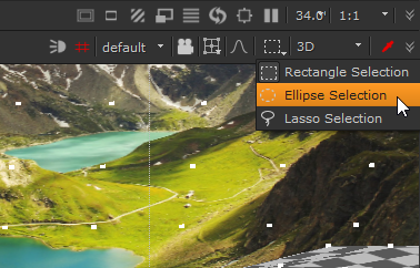
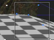
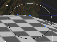
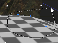
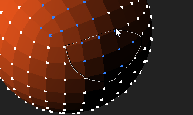
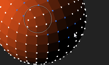
Nuke features three selection modes, Rectangle, Ellipse, and Lasso. Selection modes work the same in all Viewer contexts, whether you're selecting vertices, faces, or objects. The selection mode dropdown is located above the Viewer at the top-right.
|
|
|
|
|
Rectangle |
Ellipse |
Lasso |
Each mode uses the same selection modifiers:
• Shift - additive selection. Holding Shift and selecting vertices, faces, or objects adds the selection to any existing selection.
• Alt + Shift - subtractive selection. Holding Alt + Shift and selecting vertices, faces, or objects removes the selection from any existing selection.
Soft Selection
Soft selection makes it easier to make subtle changes to geometry in the 3D Viewer, creating soft transitions in your geometry modifications using EditGeo or ModelBuilder. See Modifying Object Shapes and Using ModelBuilder for more information.
When enabled, selecting vertices or faces in the Viewer adds additional selections according to a Falloff Radius and Falloff Curve in the Viewer's node Properties > 3D tab under Soft Selection. Soft selection includes preset falloff selection curves, such as Linear and Steep In, and allows you to create custom curves.
To enable soft selection, click ![]() above the 3D Viewer and then select the target vertices or faces. Dragging the transform handle adjusts the selected vertices or faces along with the additional selections described by the falloff.
above the 3D Viewer and then select the target vertices or faces. Dragging the transform handle adjusts the selected vertices or faces along with the additional selections described by the falloff.
Tip: You can also enable soft selection by pressing N in the Viewer.
|
|
|
|
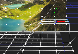
Falloff disabled on a Card |
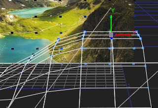
S-shape falloff enabled on a Card |
The Viewer F and H keyboard shortcuts also work with selections:
• Pressing F focuses the Viewer differently depending on selection:
• If you have vertices or faces selected, pressing F focuses the Viewer on the selection.
• With no selections in the Viewer, pressing F focuses on the whole scene.
• Pressing H focuses the Viewer differently depending on the view mode:
• If you're using a custom camera, pressing H switches the view to the camera view.
• In any view with the default camera, pressing H focuses on the whole scene, the same as pressing F with no selection.
Controlling Selection Falloff
Selection falloff determines how vertices or faces farther away from your selection are affected by changes to the geometry. The greater the Falloff Radius, the more you affect remote vertices or faces. You can use one of the built-in Falloff Curve presets, such as Linear or Steep In to modify selection more accurately or create your own curve from scratch.
| 1. | Add your selection to the Viewer using the EditGeo or ModelBuilder nodes. |
| 2. | Press S in the Viewer to display the Viewer node Properties panel. |
| 3. | Click the 3D tab and then open the Soft Selection properties. |
| 4. | Select the required Falloff Curve and then adjust the Falloff Radius to update the selection falloff. |
|
|
|
|
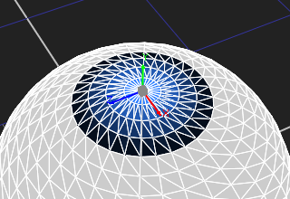
Low radius with a Linear curve |
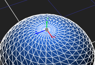
Default radius with a Linear curve |
OR
You can hold the N key over the Viewer and then left-click and drag or middle-click and drag to control the falloff.
|
|
|
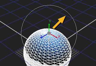
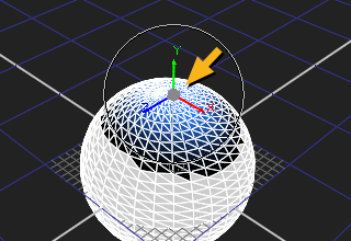
Note: Left-click and drag remembers the extent of the Falloff Radius between operations, but middle-click and drag always starts from a Falloff Radius of 0.
| 5. | Adjust your geometry as required. |
|
|
|
|
Low radius with a Linear curve |
Default radius with a Linear curve |
Selecting Nodes
You can select nodes with the Node selection tool ![]() . This is the default selection tool, and corresponds to the familiar way of selecting 3D object nodes in the Viewer.
. This is the default selection tool, and corresponds to the familiar way of selecting 3D object nodes in the Viewer.
Selecting Vertices on a 3D Object
You can select vertices on a 3D object using the Vertex selection tool. To save selections into your script, you need to use the GeoSelect node. You can find the 3D selection tools in the top right corner of the Viewer.
Note: The selection mode is set by the Viewer - changing geometry nodes translates your selections to the new object.
You can also use the Vertex selection tool to edit geometry using the EditGeo node. See Modifying Objects Using the EditGeo Node.
To select vertices in the Viewer
| 1. | Attach a 3D object to the Viewer and activate the Viewer’s 3D mode. |
| 2. | Click the Vertex selection tool |
| 3. | Select vertices on the object by dragging a marquee over the vertices you want to select. |
| 4. | By default, a new selection replaces an existing one, but you can also add and remove from an existing selection: |
• To add to existing selection, hold down Shift while selecting.
• To remove from existing selection, hold down Shift+Alt while selecting.
| 5. | You can also include hidden items by selecting the occlusion test button |
To Save or Restore Selected Vertices Using the GeoSelect Node
With the default Viewer 3D selection tools you can only make a temporary selection. To save or restore a selection, you can use the same 3D selection tools in the Viewer with the GeoSelect node:
| 1. | Create a GeoSelect node (3D > Modify > GeoSelect) and attach a 3D object to its input. The GeoSelect properties panel needs to be open in order for you to use the node for selecting vertices. |
| 2. | Click the Vertex selection tool |
| 3. | Select vertices on the object by dragging a marquee over the vertices you want to select. |
| 4. | By default, a new selection replaces an existing one, but you can also add and remove from existing selection: |
• To add to existing selection, hold down Shift while selecting.
• To remove from existing selection, hold down Shift+Alt while selecting.
| 5. | In the GeoSelect properties panel, you can also uncheck the selectable box to freeze your selection so it can’t be changed. Checking the box again enables selection again and you can continue selecting vertices as normal. |
| 6. | With the display and render controls you can select the display option you want for your object. For more information on these controls, see Object Display Properties. |
| 7. | When you’re happy with your selection, click save selection to store the vertices in the GeoSelect node. |
| 8. | The vertices are saved by the GeoSelect node and can be restored by clicking restore selection. |
Selecting Faces on a 3D Object
You can select faces on a 3D object using the Face selection tool ![]() . Each 3D object is divided into polygonal faces by wireframe lines, and with the Face selection tool you can select one or many of these.
. Each 3D object is divided into polygonal faces by wireframe lines, and with the Face selection tool you can select one or many of these.
You can also use the Face selection tool to edit geometry using the EditGeo node. See Modifying Objects Using the EditGeo Node.
| 1. | Click the Face selection tool to activate it. It is disabled by default. |
| 2. | Select faces on the object by dragging a marquee over the faces you want to select. |
| 3. | By default, a new selection replaces an existing one, but you can also add and remove from existing selection: |
• To add to existing selection, hold down Shift while selecting.
• To remove from existing selection, hold down Shift+Alt while selecting.
|
|
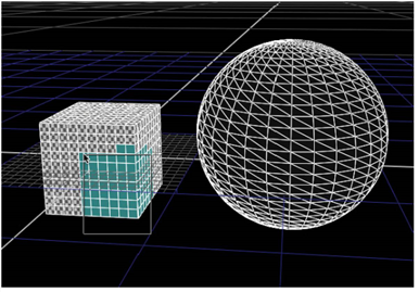
| Marquee-selecting faces on a cube. |
Selecting 3D Objects
When you have more than one 3D object in one node (such as in a case when you’re reading in a .fbx file with multiple objects), you can use the Object selection tool ![]() to select them. To select objects, activate the Object selection tool and click on the object you want to select in the 3D view.
to select them. To select objects, activate the Object selection tool and click on the object you want to select in the 3D view.
Matching Position, Orientation, and Size to 3D Selection
You can match the position, orientation, and size of a 3D object, such as a Card node, to your selected vertices in another object. Do the following:
| 1. | Click the snap dropdown menu  on the properties panel of the 3D object you want to move and select Match selection position. The object is now positioned to match the selected vertices. on the properties panel of the 3D object you want to move and select Match selection position. The object is now positioned to match the selected vertices. |
| 2. | If you select snap > Match selection position, orientation, your 3D object is positioned and aligned according to the 3D vertex selection. |
| 3. | If you select snap > Match selection position, orientation, size, your 3D object is positioned, aligned, and scaled according to the selected vertices. |