Command Regions
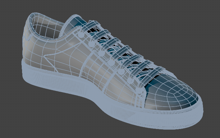
Command regions allow you to execute commands or scripts and to select other items in the scene by clicking on areas of a mesh. Command regions are defined from a selection of polygons on a Mesh item and can be assigned a color to help identify them in the 3D views.
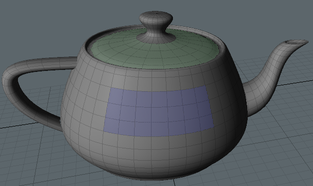
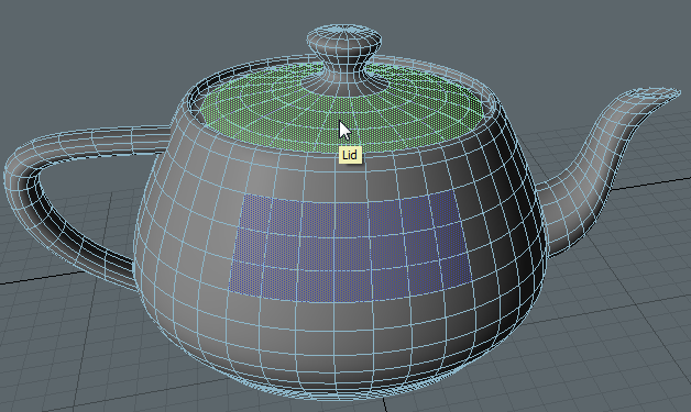
Command regions are always visible in Polygon Selection mode, but in Item Selection mode, they are only drawn when the pointer moves over the mesh they belong to. Holding the pointer over a region in Item Selection mode displays the command region's name in a tooltip.
|
|
|
| Command regions in Polygon Selection mode. | Command regions in Item Selection mode. |
Assigning Command Regions
The first step is to select the polygons to include in the region in Polygon Selection mode:
| 1. | Make sure you're in the Setup layout, so that the Controls tab is displayed on the left of the viewport. |
| 2. | Enable Polygon Selection mode in the viewport by navigating to Select > Polygon in the menu bar, clicking the Polygon Selection mode icon, or pressing 3 on your keyboard. |
| 3. | Select the polygons you intend to assign as a command region. |
Tip: Don't worry if you miss a few polygons, you can add them to the command region once it has been created. See Editing Command Regions for more information.
| 4. | In the Controls tab, under the Command Regions menu, click Assign Command Region. |
The Assign Command Region dialog displays.
| 5. | Enter the required information into the dialog: |
Note: Although Item to Select and Command to Execute are optional, you must use one or the other to successfully create a Command Region.
- Name - Enter a descriptive name for the new command region. The name must be unique on the Mesh Item that the polygons belong to. A dropdown to the right of the Name field lists all the names currently assigned to command regions on the mesh - if a name is chosen from this menu, you must edit it so that it is unique.
- Item to Select - An optional item to select can be chosen from the dropdown. This item is then selected before any command or script is executed. There are a few restrictions on which items can be selected by command regions:
The item must have a unique name. The automatic names given to items by Modo are not allowed, including numeric suffixes added by Modo.
- The Mesh Item the polygons belong to cannot be used. This item may be displayed in the dropdown menu as it's impractical to exclude it, but an error is displayed if it is selected.
- Command to Execute - Specifies an optional command or script. The dropdown to the right of the field lists a few common commands followed by all the commands currently assigned to command regions on the mesh.
- Drawing and Rollover Color - Select a color to draw the command region and its rollover highlight. Clicking on the color control opens a color picker.
Tip: To run a script, rather than a command, prefix the script name with @.
| 6. | Click OK to assign the selected polygons to the command region. |
A confirmation dialog displays.
| 7. | Take a moment to confirm your choices and click Yes to create the Command Region. |
The Command Region is created.
Assigning Command Regions in the Schematic Viewport
If you prefer to work with the schematic viewport in the Setup layout, you can also assign Command Regions with the following method:
| 1. | Make sure you're in the Setup layout, so that the Controls tab is displayed on the left of the viewport. |
| 2. | Enable Polygon Selection mode in the viewport by navigating to Select > Polygon in the menu bar, clicking the Polygon Selection mode icon, or pressing 3 on your keyboard. |
| 3. | On the schematic viewport, click Add and search for Polygon Command Region. |
| 4. | Double-click Polygon Command Region to add it to the schematic viewport. |
| 5. | Select the polygons on the mesh you intend to assign as a command region. |
| 6. | In the Controls tab, click Add Polygons under Nodal Command Regions. |
The polygons are added to the Command Region.
Note: Double-click the yellow diamond on the Geometry input of the Polygon Command Region node to expose the input mesh data.
Note: Enable Command Region in the Controls tab when you want to see Command Regions on your meshes and execute commands with them.
Tip: If you want to change the color of the command region, click the Polygon Command Region in the schematic viewport and change the color with the Color option in the Properties.
Tip: You can also assign edges and vertices to Command Regions.
Disabling Command Regions on a Mesh
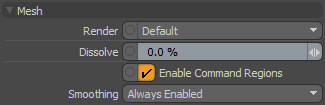
Command regions on a mesh are enabled by default, but you can disable the command region by disabling the Properties > Mesh > Enable Command Regions control.
Editing Command Regions
Once you have assigned one or more command regions, you can edit them using the controls in the Command Regions tab to the left of the viewport.
Selecting Regions
You can select regions by clicking the colored region in the viewport, or you can use the Select by Name button in the Controls tab on the Setup layout to automatically select, deselect, or invert a selection within a region.
The buttons under Select by Name provide the same options:
|
Icon |
Name |
Description |
|---|---|---|
|
|
Select Set |
Selects all polygons belonging to command regions that have polygons in the current selection. Those that were not assigned to a command region are dropped from the selection. |
|
|
Select Add |
Selects all polygons belonging to command regions that have polygons in the current selection, keeping any other polygon selections. |
|
|
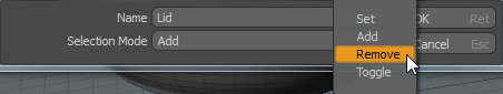
Select Remove |
Removes all polygons from the selection that are assigned to command regions. |
|
|
Select Toggle/Invert |
Selects all polygons belonging to command regions that have polygons in the current selection, dropping the original selection. Selected polygons which do not belong to a command region are not affected. |
Adding Polygons to Command Regions
Polygons can be added to existing command regions or reassigned to a different region by clicking Add Polygons.
| 1. | Select the polygons that you want to add or reassign along with one or more polygons belonging to the target command region. |
| 2. | Select the command region in the schematic viewport where you want to add the polygons. |
| 3. | Click Add Polygons under Nodal Command Regions in the Control tab. |
The new polygons are added to the target region.
If there are polygons in the selection belonging to multiple regions, the polygons are added to the first region selected and a dialog displays, asking if the other polygons should be overwritten.

| 4. | Click OK to proceed or Cancel to abort the operation. |
Removing Polygons from Command Regions
Polygons can be removed from a region by manual selection or by region name:
• Select the required polygons from all regions and click Clear from Selection, or
• Click Clear by Name and select the region name to remove.
Note: Clear by Name removes the entire region, rather than a subset of polygons from within the region.
Renaming Command Regions
You can rename a command region by right-clicking the command region in the schematic viewport, and selecting Rename. Provide a new name on the command region and press Return / Enter.
Assigning Mouse Gesture Commands to Command Regions using Rig Clay
Once you've identified the faces on a mesh where you'd like to assign a Command Region, you can assign a command region gesture to the command region. A gesture allows you to define mouse movements so that when you select a command region and perform that gesture, it executes an action on any mesh property, such as the position, rotation, or scale.
For example, you could create a gesture that specifies when you click and drag your mouse in an upward motion on a command region, it moves specific faces on a mesh upward. This allows you to create complex and intuitive rigs for posing and animating characters and faces without the need for channel hauls and other controls taking up real estate in your viewport.
|
|
|
|
|
|
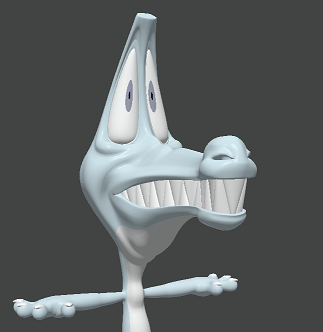
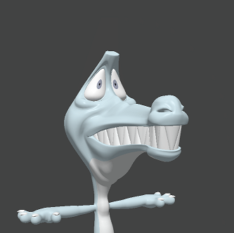
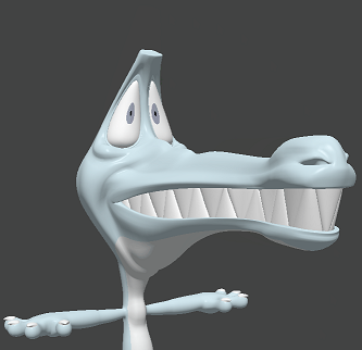
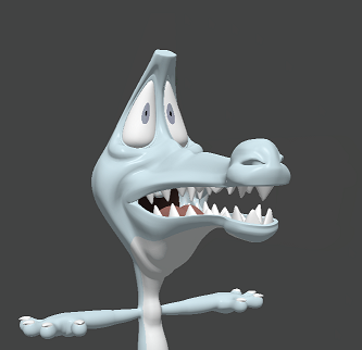
A character posed using mouse gestures and command regions on the head, nose, and teeth.
Model courtesy of William Vaughn
To assign a gesture to a command region:
- Create a command region on your mesh.
- In the Setup layout, click Add on the schematic viewport.
- Search for Command Region Gesture.
- Double-click Command Region Gesture to add it to your schematic viewport.
- Drag the output of your polygon command region and input it to the Command Region input on the command region gesture.
See Assigning Command Regions to learn how to add a command region to a mesh.
Modo creates a relationship between the command region and the command region gesture.
Note: If you can't see your command regions when you roll your mouse over, make sure Show Selection Rollovers is enabled in the Visibility tab of the 3D Viewport Properties, and that Command Regions is active in the Controls tab of the Setup layout.
Tip: You can add multiple Command Region Gestures to a single Command Region. This allows you to define multiple gestures on one Command Region to execute multiple actions.
Defining Mouse Gestures
Once you have assigned a gesture to a Command Region, you can specify what gesture is performed on the Command Region in order to trigger an event or action.
With the Command Region Gesture selected, the Properties allow you to define the behavior of the mouse gesture.
|
Option |
Description |
|
Enable |
Enables or disables the gesture. |
|
Tooltip |
Allows you to enter a tooltip that appears when the mouse hovers over the Command Region. If you have several Command Regions on a mesh, the tooltip can be used to describe what the Command Region controls. |
|
Button |
The mouse button which performs the action when pressed or held, either the Left, Middle, or Right. |
|
Mode |
Defines what kind of mouse gesture performs the action when the Button is pressed or held down:
|
|
Direction |
Defines the direction of the mouse drag when Drag is selected in Mode. The options are:
|
|
Invert |
When enabled, inverts the direction of the mouse drags. For example, by default, moving the mouse from left to right when Direction is set to Horizontal creates a positive output. When inverted, moving the mouse from right to left creates a positive output. |
|
Sensitivity |
This setting is used to control how far the mouse needs to move for an output amount on an action. A higher sensitivity results in higher output amounts. |
|
Control Multiplier |
Adjusts the sensitivity of the mouse gesture when the Ctrl/Control key is held down. For example, a Control Multiplier of 50% means when the Ctrl/Control key is held down, the sensitivity becomes 50% of what is currently defined in Sensitivity. Note: You must hold the modifier key down before you begin the gesture on the Command Region. |
|
Shift Multiplier |
Adjusts the sensitivity of the mouse gesture when the Shift key is held down. For example, a Shift Multiplier of 200% means that when the Shift key is held down, the sensitivity becomes 200% of what is currently defined in Sensitivity. |
Defining Command Region Actions
You can add an action to a mouse gesture to trigger an event or action on the Command Region. You can add commands, Channels, and Channel Sets as items to be modified by the gesture. See Command History, Channels Viewport and Channel Sets - used for collections of channels that can be viewed and modified directly in the 3D viewport as an overlay. to learn more.
The following example walks you through how to add an action that moves your mesh along the Y-axis when a mouse gesture is performed.
Note: Make sure you have a Command Region and Command Region Gesture set up for your mesh. See Assigning Command Regions and Defining Mouse Gestures to learn how.
- Select the mesh that you would like to affect in the Items list.
- Click the Channels tab in the lower-right of the layout.
- Click (add position) under the mesh name to add position channels to the mesh.
- Hold Shift and select Position X, Position Y, and Position Z and drag the selection onto the schematic viewport.
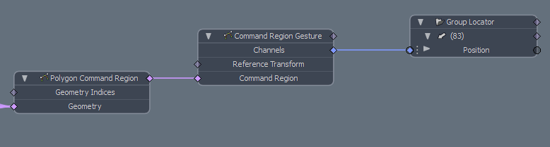
- Hover over the Position Y property on the mesh item node, right-click and select Separate Channel.
- Drag the Channels output on the Command Region Gesture to the Position Y input.
- Activate Command Region in the Control tab on the Setup layout.
Multiple meshes selected in the viewport with a Group Locator.
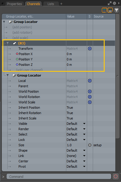
The Channels tab for the selected Group Locator showing the Position X, Position Y, and Position Z channels.
The position channels are added to the selected mesh node on the Schematic Viewport.
The Position Y property is separated from the original mesh item node and is now available to be plugged into other nodes.
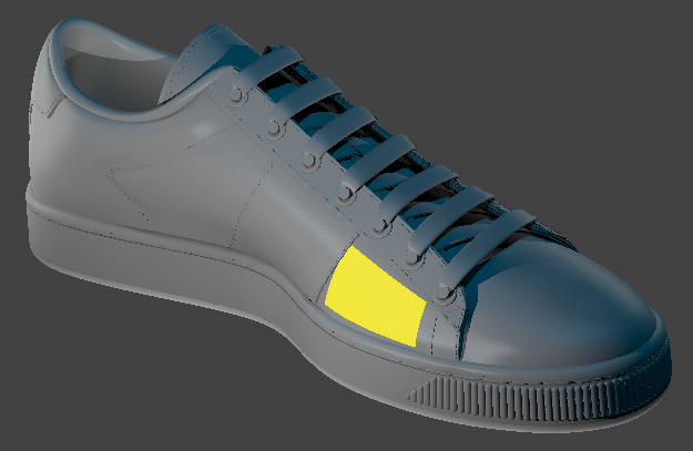
Click the yellow command region to move the mesh along the Y-axis.
Hovering over your command region and performing your defined gesture now moves the mesh item up and down along the Y-axis.
Using Mesh Operation Nodes with Command Regions
From Modo 15.0 you can set command regions on procedural meshes, making it easier to perform gestural actions to make changes quickly. The following example guides you through the minimum required nodes to establish a command region on a procedural mesh.
| 1. | Set Modo's layout to Setup. |
| 2. | In the Mesh Ops tab, click Add Operator and add a procedural mesh to your item list. For example, a cylinder. For information on adding and working with procedural meshes, go to Procedural Modeling with MeshOps. |
| 3. | In the schematic workspace, click Add... |
The Add to Schematic window opens.
| 4. | Search for a Command Region mesh operation, for example Command Region: Polygon and double click to add the node to the schematic workspace. This node is used to set the command region to a selected polygon or group of polygons on a procedural mesh. You can also set edges and vertices as command regions to procedural meshes. |
| 5. | Click Add... and add a Select by Index mesh operation node to the schematic workspace. |
| 6. | Click on the Select by Index node and go to its Properties on the right hand side. Go to Selection and type the index number of the polygon or range of polygons you want to use as the command region or use Polygon Selection mode to select polygons. |
Note: The number you enter in the Selection will depend on the number of polygons in your procedural mesh. For example, on a simple cylinder mesh, the front facing polygon might have the index number 25, but you may want the polygons in the range 21-24 as your command region. You can always change this later if you prefer.
| 7. | Click on the Command Region node and go to its Properties on the right hand side. Adjust a color channel so that your command region is more visible. For example, to set this command region as green, adjust the values of just the green channel. |
| 8. | Link the Select by Index node to the Selection attribute on the Command Region node in the schematic. |
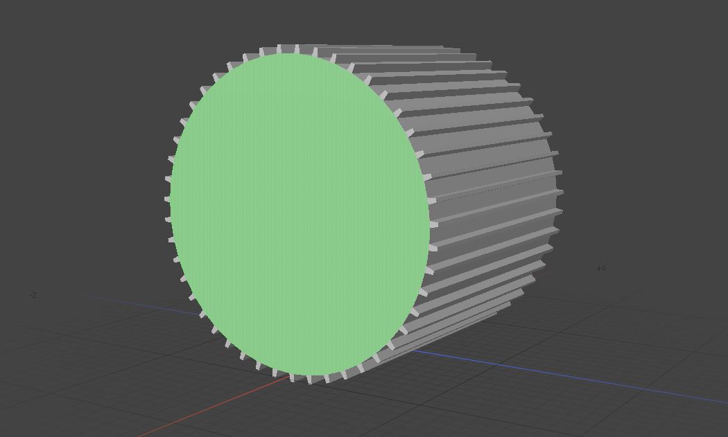
The command region on this procedural mesh is set to a single polygon and the color set to green.
| 9. | In the Control tab on the left hand side of the Setup layout, make sure the Command Region button is active. |
In Item Selection mode, each time you hover the cursor over your command region, it highlights the color set in the Properties of the Command Region node.
| 10. | Now you can add a Command Region Gesture node and link it to the Command Region node to assign a mouse gesture to your command region. See Assigning Mouse Gesture Commands to Command Regions using Rig Clay for more information. |
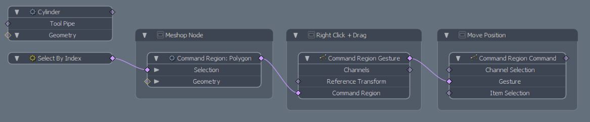
At a minimum, your schematic would look like the above example. Backdrop nodes have been added to label each node in this case.